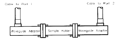
Connect the two waveguide flanges together (with the sample holder between them).

Press TRANSMISSION.
Make all four s-parameter measurements, two forward and two reverse.
Press TRANS. DONE when all four softkey are underlined.
This example assumes the following hardware configuration:
Cable connected to PORT 1
Waveguide adapter connected to PORT 1 cable
Cable connected to PORT 2
Waveguide adapter connected to PORT 2 cable
Sample holder connected to PORT 2 waveguide adapter
The first step in setting up the system for calibration and measurement is to select the frequency range (a start and stop frequency, number of frequency points and sweep type).
The measurement frequency range:
Must match the calibration frequency range
Can be as wide as the bandwidth of the cal kit
Can be just part of the bandwidth of the cal kit
However, an easy way to do this is to use the Lookup table feature.
1. Click Measure, then Define Measurement, then Lookup Table.
Select X-Band Waveguide, then click Apply.
With all three boxes checked on that dialog, this enters the correct Frequency range, cut-off frequency, and air-gap parameters.
2. Click Measure, then Define Measurement, then Sample Holder.
For Sample thickness, enter .354 inch.
3. Click Measure, then Define Measurement, then Measurement Model. Select Ref/tran u&e.
Note: Calibrate the system with the sample holder in place whenever possible. This is the reason the sample holder length is set to zero. This technique removes uncertainties in sample holder length and to a first order removes sample holder loss. For details, refer to Sample and Sample Holder Considerations.
The calibration consists of measuring known standards and using the results to characterize the three major sources of measurement error. A full 2-port calibration consists of reflection, transmission, and isolation measurements. Isolation should be omitted in most instances. The default calibration standards are a pair of short circuits, a “thru,” and a load.
The shorts are
a flush short and a ¼ wavelength offset short, or
a 1/8 and 3/8 wavelength offset short
The “thru” consists of simply butting the two waveguide flanges together
Loads may be fixed, sliding, or offset.
Note: In the following example, softkey and hardkey names may vary from cal kit to cal kit and from analyzer to analyzer. Consult the network analyzer manual for details.
To begin the calibration, on the network analyzer,
Press Local CAL CAL KIT USER KIT. The user kit should be defined as WR-90 (see network analyzer manual).
Press Cal CALIBRATE MENU FULL 2-PORT REFLECT’N to enter the first part of the calibration sequence.
Cable movement degrades measurement accuracy. Before you calibrate, immobilize the cables and adapters: lay the cables flat on a work surface or hold them in place.

Note: Measurement degradation can result from changing the position of the cable between calibration and measurements. Keep such changes and flexures to a minimum.
The reflection calibration softkeys should now be visible on the network analyzer display. The top softkey is labelled “S(11): SHORT.” S11 means it is a reflection measurement at PORT 1.
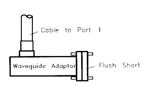
Connect a flush short to the PORT 1 waveguide adapter.
Press S11: SHORT to measure the short.
Remove the short when the analyzer beeps or underlines the softkey label.

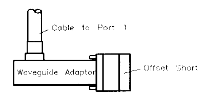
Connect a ¼ wavelength offset short to the PORT 1 waveguide adapter.
Press ¼ OFFS (immediately below the “(S11): SHORT” softkey) to measure the short.
At the beep or underline, remove it.

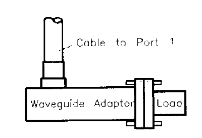
Connect the fixed load to the PORT 1 waveguide adapter.
Press FXD LOAD (immediately below the previous softkey) to measure the fixed load.
At the beep and underline, remove it.
Use the same three standards and the next three softkeys (in the S22 group) to calibrate PORT 2 as above. Whereas the standards were connected directly to the waveguide adapter at PORT 1 of the analyzer, at PORT 2 connect the standards to the sample holder attached to the waveguide adapter.
Press REFLECT’N DONE after you have measured all of the standards once at each port (waveguide flange).
Connect the two waveguide flanges together (with the sample holder between them).

Press TRANSMISSION.
Make all four s-parameter measurements, two forward and two reverse.
Press TRANS. DONE when all four softkey are underlined.
Finish the calibration without isolation.
Press ISOLATION, OMIT ISOLATION, ISOLATION DONE and DONE 2-PORT CAL.
The network analyzer calculates the error-correction numbers and displays the notation “C2” at the upper left of the display when done.
You are now ready to measure a sample.