The software assumes that the sample holder is well matched and has negligible loss. Only the phase shift of the known lengths of transmission line is accounted for. Use only a precision, well-matched sample holder. Connect it to PORT 2 prior to calibration. Any reflections off the input or output of the sample holder will degrade the calculated material parameters.
For best measurement results, the sample should fill the cross-section of the transmission line with no air gaps.
Coaxial sample holders have the inherent advantage of being broadband. They are however, typically harder to construct for the ease of sample loading. Coaxial samples also require more preparation.
Waveguide sample holders are limited to use in the waveguide frequency band. However, they can be easy to fabricate and require less sample preparation.
Free space samples should be flat; material preparation may be unnecessary. This type of material measurement is broadband. Rather than the material being contained within a transmission line, antennas radiate energy through the sample. Air gaps are not a problem with this technique.
An example is the Swissto12 THz Fixture.
Some mm-wave settings need to be applied in the PNA before the N1500A application is started. To preserve these settings, clear the Always Preset Instrument setting on the Preferences dialog.
When selected, calibrate the fixture using the Corrugated Waveguide Response Calibration Wizard.
The sample holder length, distance to sample, and sample thickness are entered in the Measure menu, Define measurement selection. The thickness and distance information needs to be characterized as accurately as possible.
This is the length of transmission line added to the measurement path after calibration. For both coaxial and waveguide lines, it is the distance between the outer conductor mating surfaces. In other words, it is the actual length added to the transmission path when the sample holder is tightened in place. It should be calibrated out or precisely measured.
To calibrate out the sample holder length, connect the sample holder to PORT 2 during calibration as shown below. Then calibrate the system using the sample holder as one of the calibration reference planes. Note that since additional transmission line is not added after calibration, the holder length is 0 (zero).
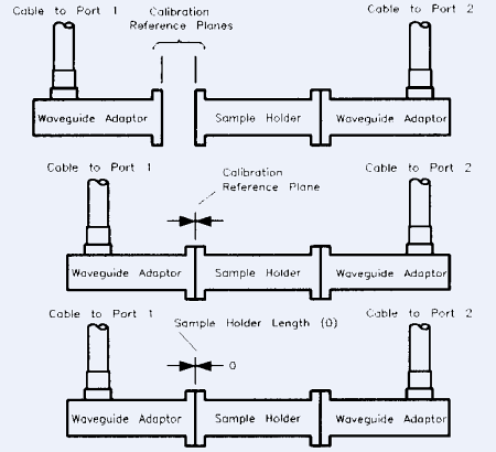
To reduce measurement uncertainties due to the sample holder:
Use a well-matched sample holder with minimum loss.
Calibrate with the sample holder at PORT 2.
If you add the sample holder after calibration, match its length to that of the sample if possible.
To calibrate without the sample holder in place, measure the holder mechanically as precisely as possible. Enter this length in the sample holder menu. As shown below, the calibration reference planes are the ends of the waveguide adapters (or coax cable ends).
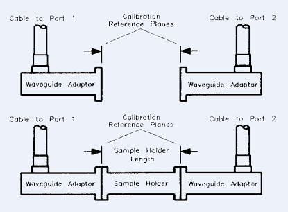
To verify the sample holder length after calibration:
Attach the sample holder to the calibration reference planes.
Measure the sample holder empty.
If the dielectric constant is calculated as about 1.0006 (air), the length is correctly entered.
If the value is not about 1.0006, vary the entered length and use the recalculate feature to close in on the correct number.
If the value does not approach 1.0006, recalibrate the system.
This dimension is the distance from the PORT 1 calibration reference plane to the sample. It should be precisely measured when required by the model. Any inaccuracy in this distance causes the “rotated” S-parameters to be in error. This is the most difficult distance measurement to make in that the sample must be loaded in the sample holder to measure the distance. Some of the models do not depend on precisely knowing the position of the sample in the sample holder.
In many cases, the simplest way to determine the distance to sample is to place it flush with the port 1 calibration reference plane. Then the distance is simply 0 (zero), and 0 should be entered in the sample holder menu.
Rotated S-parameters: Since the sample holder is zero the measurement is referenced to the end of the cables (the calibration reference plane). The rotated measurements are referenced to the surface of the sample.
For example:
Sample holder: 0 mm (sample holder calibrated out)
Distance to sample: 4 mm
Sample length: 2 mm
S11 is rotated by 8 mm (2 times distance to the sample),
S22 is rotated –12 mm (2*(sample holder length – sample thickness –distance to sample))
S12/S21 is rotated by -2 mm (sample holder length – sample thickness).
See Also: Sample Thickness Calculator
This should be measured by the most accurate mechanical means available (micrometer, vernier caliper, etc.). Uncertainty in the sample thickness will cause inaccuracies in the calculated materials parameters. The inaccuracy due to thickness errors increases with frequency and increases with the magnitude of ![]() and
and ![]() .
.
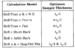

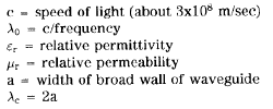
where, for ![]() mode in rectangular waveguide:
mode in rectangular waveguide:
These include sample composition and fit. It is important that the sample be uniform and completely fill the guide in the transmission line sample holder. Any air gaps between the sample and the center or outer conductor will cause measurement errors. The sample should fit tightly in the holder and be free of nicks.
Gaps between the sample and its transmission line holder may dominate the uncertainties of the measurement, especially for high permittivity materials. The air gap correction function of the software moderates this effect. This function is part of the Measure menu, Define measurement.
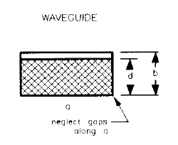
Air gap correction applies to coax and waveguide measurements, not free space. It is based on work presented in NIST technical note 1355 .