
Click Measure to show the following choices:
Recalculate
Channels (separate topic)
Sample Thickness (separate topic)
Omit calibration check
This choice causes a measurement to be triggered.
When Reflection-Only Epsilon Arbitrary-Backed Model is selected (on the Measurement Model dialog), the following appears.
This model requires two measurements.
With the sample holder with only the backing
With the sample backed.
When both measurements are made, press Calculate to cause the material parameters to be calculated.
When Reflection-Only Mu and Epsilon Single/Double Model (on the Measurement Model dialog) is chosen, the dialog box below will appear.

This model also requires two measurements. After both measurements, pressing Calculate will cause the material properties to be calculated.
This choice starts a new VNA sweep with uncertainty.
Note: Only the Nicholson-Ross model supports uncertainty and the VNA must have Option 015 (S93015A/B).
Click and the following choices appear:
Retrieve Similar to Trigger Measurement except a new measurement is not triggered. The existing measurement is used.
Retrieve
with pause The same as Retrieve
except the following dialog box (for S11) appears for each of the
required S-parameters.

Import Loads an *.s2p, *.ts (touchstone 2.0), or *.sdatcv (METAS sdatcv) file that contains 2-port measurement data.
The following describes the ports to which the imported data is applied.. When an *.s2p file is imported with its 1st port set to a and its 2nd port set to b, the N1500A software uses S11 in the file to override Saa, S12 to override Sab, S21 to override Sba, and S22 to override Sbb.
The following N1500A models are NOT supported because these models require two separate measurements:
Reflection-only epsilon arbitrary-backed model
Reflection-only mu and epsilon single/double thickness model
Two transmission mu and epsilon model.
It will have uncertainty data only when an *.sdatcv file is imported.
Selecting this choice causes a dialog box with the following tabs to appear.
The Lookup table property page allows many of the selections to be made for a variety of common coaxial and waveguide transmission lines. Select the transmission line of interest, check the desired parameters and click Apply. The appropriate items will be changed.
The N1500A software allows more than one set of ports and data set to measured.
This dialog allows you to use any of the available analyzer ports for the 2-port measurement.
Select a port number for each of the 2 ports.
See Also: N1500A Measurement Tutorial
Several different measurement/calculation models are available. Each model has different advantages and limitations. The use of each model is determined by several factors:
Optimum sample length
Measured S-parameters
Desired measurement parameters
This is an adaptation of the classical Nicholson-Ross-Weir technique described in the literature and in Keysight Technologies Product Note 8510-3. This technique characterizes both dielectric and magnetic properties of a material sample from reflection and transmission measurements.
This model is based on recently published work by the National Institute of Standards and Technology. It is an accurate technique which is independent of the placement of the sample in the sample holder.
This is a faster technique for characterizing the dielectric constant of a material. Both the “fast” and “precision reflection/transmission epsilon” models are immune to the sample half-wavelength calculation problems found with the Nicholson-Ross-Weir technique.
This characterizes the dielectric properties of a material in a coax or waveguide transmission line backed by a short circuit (or bonded to a ground plane). It is simple and best for liquids or powders.
This characterizes the dielectric materials backed by an arbitrary but repeatable termination. It is simple and best for thin film measurements.
This is the only reflection model capable of permeability measurements. It is slow and requires two measurements. It is best for liquids or powder measurements.
Check to select the initial estimate for the models. When selected, the following dialog box will appear after the measurement is made.

Uncertainty Off - This check box turns off the uncertainty computation of any new channel.
Forward Only - Selecting this item will cause only the forward S-parameters ( S11 and S21) to be used to calculate the material parameters. This is useful for analyzers with transmission/reflection test sets.
Reverse Only - Selecting this item will cause only the reverse S-parameters ( S12 and S22) to be used to calculate the material parameters.
All - The system computes Average, Forward, and Reverse types.
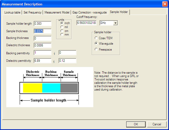
Sample Holder page allows the definition of the sample holder and sample.
Note: When Operator mode is selected in the Preferences menu, only the Sample thickness can be changed. For changing other settings, Administrator mode must be selected.
Learn all about the Sample and Sample Holder Considerations
Adjust distance to sample based on the two reflection measurements
When checked, the distance to the sample is adjusted so that the phase of the rotated reflection measurements are the same. This is done point by point. The user input is not changed. This choice is useful when the forward/reverse/average calculations do not agree.
Available ONLY when one of the following models are used:
Reflection / Transmission Mu and Epsilon
Reflection / Transmission Epsilon Precision
An uncertainty can be added to the mechanical values which can be expressed as a percentage and can have an independent coverage factor for each entry.
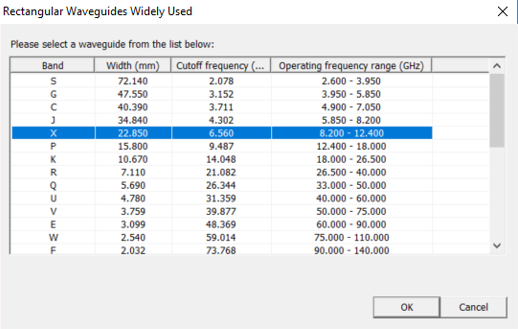
When a waveguide model is selected, rather than inserting the cutoff frequency, you can directly select the waveguide using the Find... button or you can insert the waveguide main transversal section dimension.
Deembed Check to bring up a screen that allows the measurement of a dielectric or dielectric and magnetic sample backed by a dielectric material. The backing may be on one or both sides. The thickness and permittivity of the backing material must be known.
When the Measurement Model is Stack/Tran u&e, the Sample Holder page looks like the following image:
This model is based on making two transmission measurements.
One measurement is of the sample. The sample may have a dielectric backing.
The second measurement is of the sample, backing with an additional dielectric placed on the stack. This model is useful for free-space measurements where a full two-port calibration is difficult. A two port transmission resp/isol cal is often sufficient.
Here the user does not insert the cutoff frequency but the waveguide width and then may use the Find button to get the proper waveguide.
Gap Correction allows the user to set up correction for gaps between the sample and the sample holder.
Either the Coax or Waveguide page will appear, depending on the type of Sample Holder defined.
Check Correction on to enable Gap Correction.
When the sample holder is Coax, the gap correction page looks like the following image:
When the sample holder is Waveguide, the gap correction page looks like the following image:
An uncertainty can be added to the mechanical values which can be expressed as a percentage and can have an independent coverage factor for each entry.
See How to Begin a Waveguide Calibration
This menu item allows the user to select a cal set for PNA series analyzers. The cal set for all other analyzers must be selected manually.
This menu item allows the use of the features listed below.
Perform a gated reflect line calibration from a cal set (GRL) ...
Selecting this menu item activates a wizard that guides the user through a gated reflect line calibration. This feature creates a freespace cal set from an existing coaxial/waveguide cal set by measuring a metal plate and an empty fixture. It also makes the measurements required for a gated response isolation cal, which can be performed independently by selecting the item below.
Perform a one-tier gated reflect line calibration (GRL) ...
Selecting this menu item activates a wizard that guides the user through a gated reflect line calibration. This feature creates a freespace cal set by measuring a metal plate and an empty fixture. This is done without the need of an existing coaxial/waveguide cal set as required by the ‘Perform a gated reflect line calibration from a cal set (GRL) ...’ selection. It also makes the measurements required for a gated response isolation cal, which can be performed independently by selecting the item below. This technique usually requires a greater number of measurement points than the ‘Perform a gated reflect line calibration from a cal set (GRL) ...’ selection. See GRL Measurement Considerations for additional information.
Perform two port transmission resp/isol cal…
Selecting this menu item will guide the user through and create a full two-port calibration based on measuring response and isolation standards. The various match imperfections will be assumed to be perfect. This calibration is useful when using the Tran e Fast or Stack/Tran u&e models and a free-space fixture.
Perform gated resp/isol cal…
Selecting this menu item activates a wizard that guides the user through a gated response isolation calibrated.
Apply gated resp/isol cal
This menu item allows the user to toggle on and off the application of a gated resp/isol cal to the next measurement.
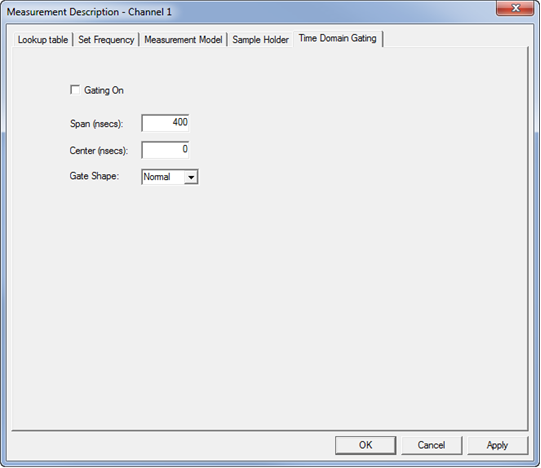
When viewing the time domain response of a device, the gating function can be used to "virtually" remove undesired responses.
Gating On - Check to turn gating on.
Span - Specifies the range to either side of the center value of the area affected by the gating function.
Center - Specifies the value at the center of the area that is affected by the gating function.
Gate Shape - Defines the filter characteristics of the gate function. Choose from Minimum, Normal, Wide, Maximum. Learn about Gating in the PNA. Requires an internet connection.