Physical layer test systems can provide measurement-based frequency domain information in two ways:
Making frequency domain measurements directly utilizing a vector network analyzer (VNA) and an S-parameter test set to sweep the DUT with an RF signal and measuring the RF response.
Making the time domain measurements utilizing a Time Domain Reflectometer (TDR) to apply a synthesized step waveform to a DUT and observing the response. Then the measured time domain information is converted to the frequency domain using the Fast Fourier Transform (FFT).
In a linear network, the Fourier Transform describes the relationship between a time domain measurement and its corresponding frequency domain response in detail. Therefore, given the measured time domain response of a DUT, it is possible to determine its frequency domain response mathematically by performing a Fourier Transform.
There is information to be gained from the frequency domain that other analysis types do not provide. Frequency domain information can help you verify and validate your modeling and simulation procedures by providing:
Vector error-corrected data which allows you to de-embed fixtures and signal launches
More accurate simulation for frequency dependent effects, such as bandwidth and impedance
Insight into common analog problems, such as crosstalk, reflections, and loss
Better information more efficiently when you are analyzing the effects of transmission lines, studying power/ground distribution, and investigating EMI effects as a function of frequency
S-parameter data which can be used over the widest range of applications and frequency bandwidths
At high frequencies, S-parameters (scattering parameters) are commonly used to describe the performance of microwave and RF devices. These parameters can be used to completely describe the electrical behavior of the device (or network). For those not familiar with S-parameters, they are simply the energy that is reflected off of, or transmitted through, a device under test. While S-parameter data is formatted differently than TDR/TDT data, the underlying information is the same.
S-parameters relate to familiar measurements such as reflection coefficient (input/output match), and transmission coefficient (gain or loss, and isolation). They are the shared language between simulation and measurement and are easily imported into electronic-design automation (EDA) tools like HSPICE, ADS, and other simulators.
Conventional single-ended parameters describe the performance of a single-ended device when it is stimulated on a single port, and the corresponding responses are observed on all of the ports. For a detailed explanation, refer to Single-Ended (Unbalanced) S-Parameters. Mixed-mode (or balanced) S-parameters describe the performance of devices with balanced ports. For a detailed explanation, refer to Mixed Mode (Balanced) S-Parameters.
|
Reflection Measurements |
Transmission Measurements |
|
Return Loss |
Insertion loss |
|
Standing Wave Ratio (SWR) |
Gain/loss |
|
Reflection coefficient |
Transmission coefficient |
|
Impedance |
Electrical delay |
|
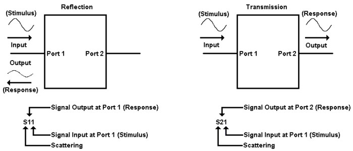
Sxx (x = stimulus port and response port) |
Syz (z = stimulus port, y = response port) |
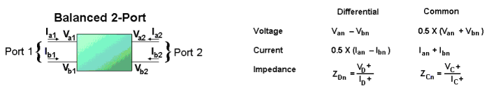
A multi-terminal device can be viewed in different ways, depending on how it is meant to be operated. For a device that is designed to be a single-ended four-port device, its conventional (single-ended) four-port S-parameters can be measured and displayed. In a balanced device, two terminals constitute a single balanced port. Each balanced port will support both a common-mode and a differential-mode signal. This performance is described using mixed-mode (balanced) S-parameters.
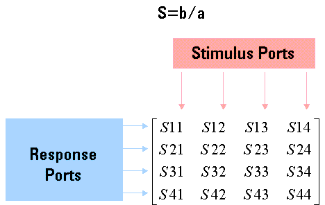
Conventional single-ended S-parameters are defined as the ratio of two normalized power waves (response/stimulus), defined in terms of the voltages and current at each port of a device. S-parameter notation identifies these quantities using the following convention:
SAB
where:
The first number (represented by A) refers to the test-device port where the signal is received. This received signal is referred to as the response.
- and -
The second number (represented by B) refers to the test-device port where the signal is sourced. This signal is referred to as the stimulus.
The following shows the naming convention for a single-ended 4-port S-matrix, showing the ratio of all possible combinations of response/stimulus.
Mixed-mode S-parameters are used to describe the performance of balanced circuits by independently considering each mode of operation. The mixed-mode S-parameter concept is similar to conventional S-parameter definitions, except that instead of stimulating a single terminal of the DUT, we consider pairs of terminals to be stimulated in either a differential (anti-phase) or a common (in-phase) mode.
For a balanced device, we are not necessarily interested in voltages and current referenced to ground. Instead, we can define differential and common mode voltages and currents on each balanced port. Likewise, we can also define differential-mode and common-mode impedances.
We can define normalized power waves on the ports of a balanced device having the exact same form as the single-ended case. Only the definitions of "voltage" and "current" are changed. Both are defined as ratios of normalized power waves.
|
|
Normalized Power Waves |
|
|
Differential-Mode |
Common-Mode |
|
|
Stimulus |
|
|
|
Response |
|
|
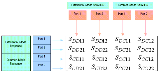
The naming convention for mixed-mode S-parameters includes mode information as well as port information. Unlike the single-ended example, though, in the mixed-mode S-matrix, we are not only considering the port, but we are also considering the mode of the signal at each port. Therefore, the first two subscripts describe the mode of the response and stimulus, respectively, and the next two subscripts describe the ports of the response and stimulus.
Again we can take the ratio of all possible combinations of response over stimulus for the differential and common mode normalized power waves to calculate the mixed-mode S-parameters. The mixed-mode matrix fully describes the linear performance of a balanced two-port measurement. The following shows the naming convention for a mixed mode S-matrix, showing the ratio of all possible combinations of response/stimulus.
mode = Differential or Common
port = balanced port number (1 or 2)
Learn how to open, view, set format, and scale Frequency domain data.