Click Utilities then Edit Cal Kits

|
Select Calibration Type Select the type of calibration kit to edit or export. If only USER_DEF appears, this indicates that NO calibration kits of that type are defined. A Cal Kit must first be defined before that type of calibration may be performed.
Export to PNA (Available ONLY with Full PNA Cal Mode) Sends the selected Cal Kits to the PNA. The Cal Kit can then be used with PLTS in Full PNA Cal Mode. |
One of the following dialog boxes appears depending on the type of Cal Kit:
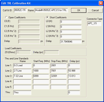
TRL - Learn more about TRL Cal
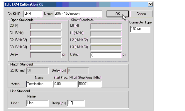
LRM
SOLT

|
Cal Kit ID, Name, and Connector Type Enter these values into the appropriate entry boxes in the header. Reflect Standard Choose either an Open or Short as the Reflect standard.
Thru and Line Standards Line Standards
Thru Standard Enter the name and delay (typically 0 ps). Select OK to save the calibration kit data and exit the dialog box. Select Cancel to close the dialog box without saving the calibration kit data. |

|
Enter Cal Kit ID, Name, and Connector Type into the appropriate entry boxes in the header. Short Delay Enter the delay value (in picoseconds) of the short standard. Match Standard: Enter the characteristic impedance (Z0) in ohms and Delay in picoseconds. Also enter a Load Name for the Match as well as the start and stop frequencies in MHz of the load. Line Standard: Enter a name for the Line along with its delay (in ps). OK Saves the calibration kit data and closes the dialog box. Cancel Closes the dialog box without saving the calibration kit data. Return to the startup wizard to complete the LRM calibration procedure. You can select New from the File menu to restart the wizard.
|

|
Enter Cal Kit ID and Name into the appropriate entry boxes in the header. Enter Connector Type along with the minimum (Min. Freq. MHz) and the maximum (Max. Freq. MHz) frequencies in megahertz. The software compares the minimum and maximum frequency entries against the measurement setup frequencies when determining which calibration kits to make available for selection for the calibration. Open Coefficients Enter the coefficient and delay values. If you are using a standard from a calibration kit, the coefficient and delay values may be found in the calibration kit documentation. The four coefficient values for the open are the capacitance in farads (F). Enter the capacitance value followed by the exponent. For example, if C0 is equal to 49.433¥10-15, the value would be entered as: 49.433E-15 Delay (in picoseconds) This value may also be found in the calibration kit documentation if you are using a standard from a calibration kit. Short Coefficients Enter the coefficient and delay values. If you are using a standard from a calibration kit, the coefficient and delay values may be found in the calibration kit documentation. The four coefficient values for the short are the inductance in henries (H). Enter the inductance value followed by the exponent. For example, if H0 is equal to -2.0765¥10-12, the value would be entered as: -2.0765E-12 Delay (in picoseconds) This value may also be found in the calibration kit documentation if you are using a standard from a calibration kit. Load Coefficients Entering the characteristic impedance (Z0) in ohms and Delay in picoseconds. If you are using a standard from a calibration kit, the coefficient and delay values may be found in the calibration kit documentation. Thru Standards First, from the Choose a thru configuration for this Cal Kit: selection, select either 4 Cross, 4 Box, or 6 Cross. The following shows the paths that will be calibrated using a thru for each selection.
Next, select either Choose Adapter File in the Characterization Data area or Delay (ps) in the Thru Delay area.
If you don't have a characterization file for the thru that you will use to calibrate, you can create one by selecting the Characterize Adapter selection in the Characterization Data area and then select the Create Custom button. This will open the Custom Adapter Characterization Wizard. Refer to Characterizing Adapters for information on the Custom Adapter Characterization Wizard.
Finally, in the list of Thrus at the bottom of this dialog box, select the box at the left of the thru and click the Add button to associate the thru to either the selected adapter file or to the entered delay value. The color of the box at the left of the thru changes from red to green as the thru path is completed. Enter a selected adapter file or a delay value for each thru path. All or the thru paths may use the same characterization file or delay value or each may have a different characterization file or delay value depending on your calibration requirements. OK Saves the calibration kit data and closes the dialog box. Cancel Closes the dialog box without saving the calibration kit data. Return to the startup wizard to complete the calibration procedure. You can select New from the File menu to restart the wizard.
|