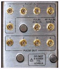
The models offer the 15 pin D connector provides access to Pulse Modulators and Generators.
See IF Path Configuration Dialog and block diagram, which includes the Pulse Modulators and Generators.
|
Pin |
Name |
Description |
|
1 |
IFGateAIn |
IF pulse gate input A (TTL) |
|
2 |
IFGateBIn |
IF pulse gate input B (TTL) |
|
3 |
IFGateCIn |
IF pulse gate input C (TTL) |
|
4 |
IFGateDIn |
IF pulse gate input D (TTL) |
|
5 |
IFGateRIn |
IF pulse gate input R (TTL) |
|
6 |
DCOM |
Ground |
|
7 |
PulseSyncIn |
Pulse gen. synchronization trigger input (TTL) |
|
8 |
RFPulseModIn |
RF source pulse modulation drive input (TTL) |
|
9 |
DCOM |
Ground |
|
10 |
Pulse1Out |
Hardwired pulse train output #1 (TTL) |
|
11 |
Pulse2Out |
Hardwired pulse train output #2 (TTL) |
|
12 |
Pulse3Out |
Hardwired pulse train output #3 (TTL) |
|
13 |
Pulse4Out |
Hardwired pulse train output #4 (TTL) |
|
14 |
N.C. |
No connect -- for future use |
|
15 |
DCOM |
Ground |
See Pulse SCPI and COM commands
This D connector to RF adapter makes accessing the Pulse I/O connector more convenient.
Last Modified:
|
4-May-2011 |
Added N522x |
|
16-Jul-2007 |
Clarification |
|
18-Jan-2007 |
MX New topic |