How to start the Pulse Setup dialog
To provide quicker access, use the Setup softkey. Learn how.
Using front-panel
hardkey [softkey] buttons
Using Menus
Press Sweep
then [Pulse Setup]
Click Stimulus
- then Sweep
then Pulse Setup
![]()
The Pulse Setup dialogs shown in this topic are now integrated in the PNA firmware and are available with Opt 008 or Opt H08.
Previously, setup was performed with the Narrowband or Wideband pulse programs. With the appropriate hardware options (Opt 021, 022, 025) these commands are still available without Opt 008 or H08. Learn more about PNA Options.
Beginning with A.09.50, external pulse generators can be used along with the PNA internal pulse generators. Learn more.
In this topic
Narrowband Pulsed Application (Opt H08)
See Swept IMD note regarding IF Filter setting
App Note: Active-Device Characterization in Pulsed Operation Using the PNA-X (1408-21)
How to start the Pulse Setup dialogTo provide quicker access, use the Setup softkey. Learn how. |
|
Using front-panel
|
Using Menus |
|
|
|
|
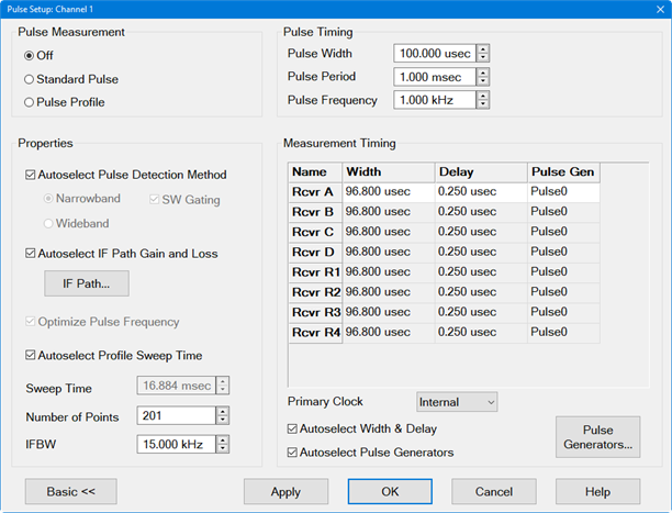
The Basic controls allow simple pulse measurements using the default (Autoselect) settings in the Advanced section of the dialog. Pulsed measurements are performed in a Standard channel. See Measurement Class. However, several PNA measurement settings are controlled by the Pulse setup, such as sweep type, number of points, and so forth. Pulse MeasurementOff - Source and Receivers are NOT pulsed Standard Pulse - With pulsed RF, the PNA can be configured to sweep in frequency, power sweep, and CW time.
Pulse Profile - Pulse profile measurements provide a time domain (CW frequency) view of the pulse envelope. Profiling is performed using a measurement technique that "walks" a narrow receiver "snapshot" across the width of the pulse. This is analogous to using a camera to take many small snapshots of a wide image, then piecing them together to form a single, panoramic view.
Pulse Profile measurement using default settings and R1 receiver.
Pulse TimingPulse Width - Sets the width of the source pulse. See measurement timing to learn how to control the receiver width and delay. Pulse Period The time to make one complete pulse. Pulse Frequency (PRF) The reciprocal of Period (1/ Period). See Internal Pulse Generators to learn more. By default, these settings configure Pulse Gen 1 to drive Source Modulators 1 and 2. This can be changed from the Advanced Settings Pulse Generator Setup dialog. -------- Advanced Settings ----------The following settings allow maximum control of a Pulse measurement. Note: When the "Auto" check boxes are cleared, it is possible to configure settings to make an invalid measurement. PropertiesAutoselect pulse detection method - check to automatically switch between Narrowband and Wideband based on the Pulse Width. In Standard Pulse:
In Pulse Profile:
Autoselect IF Path Gain and Loss - For future use. IF Path - Click to launch the IF Path dialog. Optimize Pulse Frequency - Automatically selects the Pulse Frequency and Pulse Period.
Autoselect Profile Sweep Time - In Pulse Profile mode, adjusts the default X-axis start time to zero and the stop time double the Pulse Width. This allows you to see one complete pulse. If unchecked, the Sweep Time will not be changed. To adjust the X-axis manually, click OK to close the dialog. Then click Stimulus, then Sweep, then Sweep Time, then change the Start Time and Stop Time. IFBW - Select the IFBW for the measurement.
Measurement TimingSource1 and Source2 - Used as RF Source Modulation Drive.
The receiver settings in this table change depending on whether the PNA is in Narrowband or Wideband mode.
Master Pulse Trigger Refer to Block Diagram Choose from:
The Primary Clock is controlled by the internal or external pulse generator and is the primary pulse clock. The Internal and External selections are not the same as the Trigger Source Internal and External selections found in the Pulse Trigger tab of the Trigger dialog. However, they are inter-related as follows:
Autoselect Width and Delay - When checked, for Wideband mode and Pulse Gen = Pulse Trigger, the default setting for the receiver is adjusted to approximately 75% of the source pulse width, with 20% delay. This leaves approximately 5% of the source pulse ON after acquisition is complete. When checked for Narrowband mode and Pulse Gen <> CW, then Delay and Width matches the RF Source. Autoselect Pulse Generators - When checked:
Pulse Generators Click to launch the Pulse Generators Setup dialog. |
This dialog is available with Option 025 (pulse generators). To see this dialog, press Pulse Gen Setup on the Pulse Setup dialog. Pulse GeneratorsConfigure the Pulse Generators to be used for your measurement. When configured, external pulse generators appear in this list. Learn more. Delay defines the delay between the pulse clock and when the receiver begins to make a measurement. Learn more.
Important: If D + W is greater than P, then undefined PNA behavior results. There is NO error message or warning. Invert Check to cause the pulse ON time to be active low and OFF be active high. Enable Check to enable individual pulse generators. Trigger Choose from: (When ONE of these is changed, they ALL change. The internal Pulse Generators can NOT be triggered individually).
Frequency - Set the pulse frequency of each generator.
Period - Set the period of each generator. Learn more about the Pulse Generators. Pulsed SourcesCheck to enable one or both internal source modulators. These are switches 8 and 9 in the Block Diagram Important: When internally modulating the sources, source leveling is automatically set to Open-loop (ALC Open Loop box will be checked automatically). Modulator Drive Choose the pulse generator to modulate the specified source. Choose from CW (NO pulse), Pulse 1, 2, 3, 4, External. This is switch 7 Block Diagram. Pulsed Receivers Synchronize ADCs using pulse trigger - Check to enable triggering used to gate the ADC for wideband receiver measurements. This is the same as Pulse0 Enable. The Width can NOT be configured. ADC trigger delay - Set the amount of time to wait before triggering the ADC to begin acquisition. This is the same as Pulse0 Delay. Pulse4 output indicates ADC activity - Check to use an oscilloscope connected to pin 13 of the PULSE I/O connector on the rear panel of the PNA to display when the ADC is making measurements. Pulse Trigger.. - Click to start the Pulse Trigger dialog. Trigger... - Accesses the Trigger dialog for setting up triggering. Learn more.
|
To see this dialog, press Pulse Trigger on the Pulse Generator Setup dialog or select Stimulus, then Trigger from the PNA Menu. Trigger SourceSelect Internal or External to provide sync capability for the internal pulse generators.
The external trigger input is on the Pulse I/O connector pin 7 (PulseSyncIn). The PulseSyncIn line provides a configurable trigger signal into the Pulse Generators. If the trigger mode is set to "level", and if the trigger is still valid when the first pulse set is finished, another set will be generated. Only one set of pulses is emitted when edge triggering is used. Trigger Level/EdgeSets the edge or level of the trigger signal to which the internal pulse generators will respond when being externally triggered at the PulseSyncIn pin. Positive = rising edge; Negative = falling edge. These selections are available ONLY with DSP version: 4.0 FPGA: 34 or higher. Learn more. Otherwise, the pulse generators respond only to positive, level input trigger signals. Receiver synchronizationSynchronize ADCs using pulse trigger - Check to enable triggering used to gate the ADC for wideband receiver measurements. The Width can NOT be configured. ADC trigger delay - Set the amount of time to wait before triggering the ADC to begin acquisition.
|
See complete description at IF Path Configuration
See also Using External Pulse Generators
Using External Pulse Generators
Setup the External Pulse Generator as an External Device.
To perform a calibration in pulse mode (option H08 / 008), first configure and apply the pulse parameters (PRF, Pulse Width, Delays, IF gating, and so forth) before calibrating the system. This will ensure the PNA is configured properly during the calibration and measurement.