Configuring Phase Noise

The Phase Noise dialog settings are contained within five tabs: Sweep, RF Path, Spurious, Integrated Noise, and Spot Noise.


In this topic:

See Also

Create a Phase Noise Channel

  1. On the VNA front panel, press Meas > S-Param > Meas Class....

  2. Select Phase Noise, then either:

  1. In the Confirm Measurement Class Change dialog, click OK to proceed or Cancel to exit.

  2. The Phase Noise dialog is displayed.

Opening the Phase Noise Dialog

Accessing Phase Noise Settings

Using Hardkey/SoftTab/Softkey

Using a mouse

  1. Press Setup > Main >  Phase Noise Setup....

  1. Click Stimulus.

  2. Select Phase Noise Setup....


Sweep Tab in dialog help

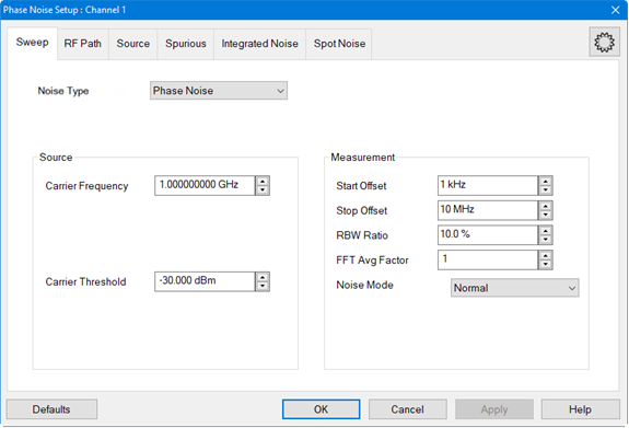
Noise Type - Selects between standard phase noise measurements and residual noise measurements.

Phase Noise -  (Default) - Measures phase noise of a DUT. Select for single channel residual noise measurement when the input and output frequencies of the DUT are not the same. For example, frequency converters.

Residual Noise - Measures the additive phase noise of a DUT. This measurement is set up in the RF Path tab using DUT Input and DUT Output. Select for 2-channel residual noise measurement when the input and output frequencies of the DUT are the same. For example, amplifiers.

Carrier Frequency - Sets the carrier frequency. The range of the phase noise measurement is determined by the start/stop offset frequency which is relative to the carrier frequency.

Carrier Threshold - Sets the threshold to use during a carrier search.

Start Offset - Sets the start frequency of the phase measurement. This is an offset relative to the carrier frequency to position the measurement about the noise sideband to measure power density in dBc/Hz. For example, if the Start Offset is set to 1 MHz with a carrier frequency of 1 GHz, then the dBc/Hz phase noise measurement starts at 1.001 GHz. The minimum frequency is 0.1 Hz.

Stop Offset - Sets the stop frequency of the phase measurement. This is an offset relative to the carrier frequency to position the measurement about the noise sideband to measure power density in dBc/Hz. For example, if the Stop Offset is set to 10 MHz with a carrier frequency of 1 GHz, then the dBc/Hz phase noise measurement stops at 1.010 GHz. The maximum frequency is 10 MHz.

RBW Ratio - Sets the resolution bandwidth ratio, which is the specified resolution bandwidth percentage of every half decade offset frequency.

Example:

Start Offset = 1 kHz

Stop Offset = 100 kHz

RBW Ratio = 10%

1 kHz - 3 kHz: RBW = 100 Hz (10% of 1 kHz)

3 kHz - 10 kHz: RBW = 300 Hz (10% of 3 kHz)

10 kHz - 30 kHz: RBW = 1 kHz (10% of 10 kHz)

30 kHz - 100 kHz: RBW = 3 kHz (10% of 30 kHz)

FFT Avg Factor - Sets the FFT average factor number. The average factor is multiplied by the default average count, which changes for each frequency range. The default average count of the lower frequency range is 1 and at the higher offset frequency range is a larger average count.

Note: The minimum RBW Ratio setting relative to the maximum FFT Avg Factor setting are limited based on the frequency offset. The firmware restricts these settings if they exceed the limits.

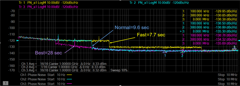
Noise Mode- Sets the measurement speed and noise floor.

Fast - Fastest measurement speed with highest noise floor.

Normal - Between fastest and slowest measurement speed and noise floor.

Best - Slowest measurement speed with lowest noise floor.

The zone boundaries and decimation factors change with noise mode as shown in the following example:
Defaults button - Restores default phase noise settings.

Apply button - Applies setting changes and leaves the dialog box open to make more setting changes.



RF Path Tab in dialog help

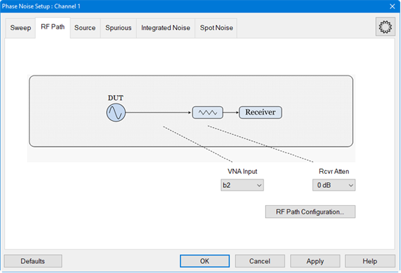
Measurement Type: Phase Noise

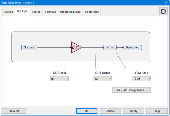
Measurement Type: Residual Noise

VNA Input - Sets the receiver input to use for the phase noise measurement.

DUT Input/DUT Output - Displayed when Noise Type in the Sweep tab is set to Residual Noise. Sets up ratios for residual phase noise measurements. For example, with DUT Input set to a1 and DUT Output set to b2, the additive phase noise at b2 relative to a1 is measured.

Rcvr Atten - Sets the attenuator on the test receiver.

RF Path Configuration... - Learn more

Defaults button - Restores default phase noise settings.

Apply button - Applies setting changes and leaves the dialog box open to make more setting changes.


Source Tab in dialog help


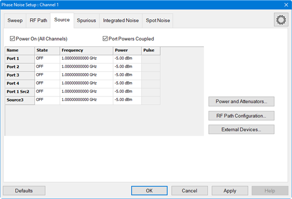
Power On (All Channels)  Check to enable source power for all channels. Only turns power ON if the port State setting is ON.

Port Powers Coupled

  • Coupled (checked)  The power levels are the same at each test port. Set power at any test port and all test ports change to the same power level.

  • Uncoupled (cleared)  The power levels are set independently for each test port. Uncouple power, for example, if you want to measure the gain and reverse-isolation of a high-gain amplifier. The power required for the input port of the amplifier is much lower than the power required for the output port. A power sweep can also be performed with uncoupled power. Learn more about Setting Independent Port Power.

Source Cells

Name - Lists the test ports through which an internal source is available. If an external source has been configured, it will appear at the bottom of the list.

State

  • ON  Source power is ALWAYS ON. Turning ON port 1 will also turn ON port 2 and vice versa. The same is true for port 3 and port 4. Learn about internal second source restrictions.

  • OFF  Source power is never ON, regardless of the measurement requirements. Use this setting to prevent damage to a sensitive DUT test port.

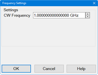
Frequency - Click in the cell, then click Edit, to start the Frequency Settings dialog (below).

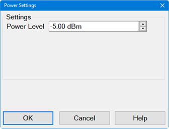
Power - Sets the power level at the output of the source. Click in the cell, then click Edit, to start the Power Settings dialog (below).

Pulse - Enable/disable pulse measurements. Learn more.

Power and Attenuator...Learn more

External Devices...Learn more


Defaults button - Restores default phase noise settings.

Apply button - Applies setting changes and leaves the dialog box open to make more setting changes.


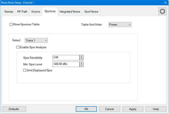
Spurious Tab in dialog help

Show Spurious Table - Enable or disable displaying the spurious table below the trace display.

Trace - Displays trace number(s).

Spur - Displays the spur number(s) per trace.

Offset - Offset frequency.

Power - Power level of the spur.

Jitter - The phase deviation in the time domain.

Table Sort Order - Sets the spurious table sorting by power or by offset.

Select -

Enable Spur Analysis - Enables and disables spurious analysis search markers. See Spurious Search.

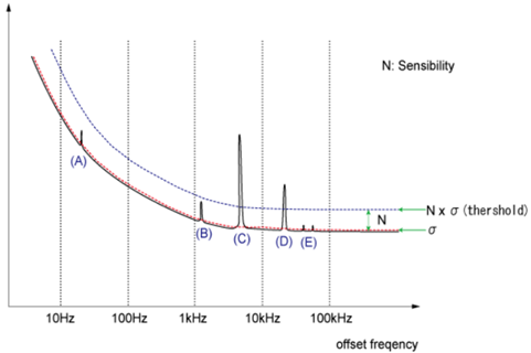
Spur Sensibility - Sets the spurious sensibility value. The default is 3 (3 x standard deviation (sigma)).

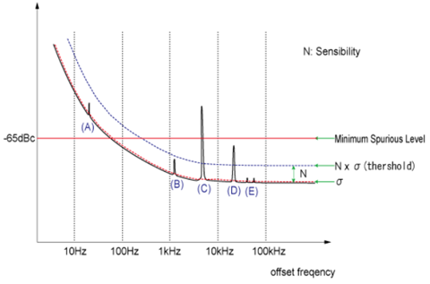
Example of Spurious Judgement Using Spurious Sensibility


Min. Spur Level - Spurious data larger than this minimum spurious level will be omitted from the spurious data.

Omit Displayed Spur - Omits all displayed spurs.


Defaults button - Restores default phase noise settings.

Apply button - Applies setting changes and leaves the dialog box open to make more setting changes.


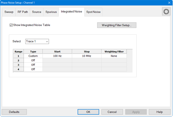
Integrated Noise Tab in dialog help

Show Integrated Noise Table - Enable or disable displaying the integrated noise table below the trace display. Integrated noise is the single sideband noise integrated over a measurement bandwidth from a start/stop frequency.

Trace - Displays trace number(s).

Start Offset - This is the same as the Start Offset defined in the Sweep tab.

Stop Offset - This is the same as the Stop Offset defined in the Sweep tab.

Weighting Filter - Displays the weighting filename or None for no weighting.

Integ Noise - Noise over a measurement bandwidth from the defined start/stop frequency.

PM - Phase Modulation measured in degrees and radians.

FM/AM - The FM/AM column displays a value depending on the measurement parameter. When the measurement parameter is Phase Noise (for example, PN_b2), the residual FM (Hz) is shown in the FM/AM column. When the measurement parameter is AM Noise (for example, AM_b2), the percentage of modulation of the carrier is shown in the FM/AM column.

Jitter - The phase deviation in the time domain.

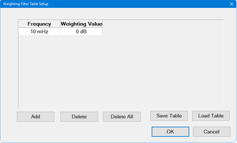
Weighting Filter Setup... button - Accesses Weighting Filter Table Setup dialog. The weighting filters compensate external effects that affect the phase noise in the specified frequency ranges. When the weighting filters are applied, the trace data are corrected by the filter characteristics before the calculation of integrated noise. You must define at least 2 frequencies when using the Weighting Filter.

Add button - Adds a frequency below existing entries.

Delete button - Deletes the currently selected frequency in the table.

Delete All button - Deletes all frequencies in the table.

Save Table button - Saves the weighting filter table to a .csv file. The file should be saved in the following directory: C:\ProgramData\Keysight\Network Analyzer\WeightingFilter. All filters saved in this directory are shown on the drop down list in the Weighting Filter column.

Load Table button - Loads a previously saved weighting filter table.

Select - Selects an existing phase noise trace or allows you to add a new trace. Each trace can have up to four defined ranges. See Displaying Phase Noise Parameters.

Range - Sets the integration range number.

Type - Sets the integration range type of the selected integration range defined as offset frequency from the carrier.

Off - Disables specific range and will not be measured.

Full Span - Enables the measurement bandwidth to be the full offset range defined in the Sweep tab.

Custom - Enables custom-defined start and stop offset range.

Start - Start offset frequency for the integrated noise measurement.

Stop - Stop offset frequency for the integrated noise measurement.

Weighting Filter - Selects pre-defined weighting filter file. Select None when a weighting filter file will not be used.

Defaults button - Restores default phase noise settings.

Apply button - Applies setting changes and leaves the dialog box open to make more setting changes.


Spot Noise Tab in dialog help

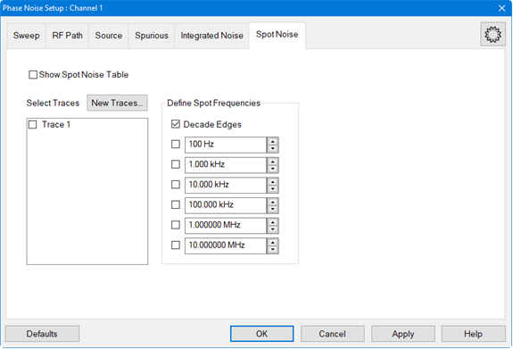
Show Spot Noise Table - Enable or disable displaying the Spot Noise Table below the trace display.

Trace - Displays trace number(s).

Spot Frequency columns - Displays decade edges and/or specified offset spot frequencies.

Select Traces - Select traces for calculating the Spot Noise.

New Traces... button - Add a new trace for calculating Spot Noise.

Define Spot Frequencies - Select the check boxes and enter specific spot frequencies to measure. A trace must be selected.  If Decade Edges is selected, the decade edges will also be measured. Duplicate frequencies between Decade Edges and Spot Frequencies are shown only once.

Decade Edges - Select to measure the decade edges based on the Start Offset and Stop Offset settings defined in the Sweep tab. Deselect to measure only the defined/selected spot frequencies. A trace must be selected.

Defaults button - Restores default phase noise settings.

Apply button - Applies setting changes and leaves the dialog box open to make more setting changes.