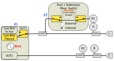
Ref#
Element Name
Settings
#1
"Src1Out1LowBand"
"Filtered"
"HiPwr"
#2
"Port1RefMxr"
"Internal"
"External"
Not shown
"PortxCoupler"
(SMC measurements only. Learn more.)
"Normal"
"Reversed"
The tables below show RF Path Configuration Elements for all PNA-X models and options. These settings are provided for configuring the elements using SCPI and COM commands.
PNA-X Opt 029
|
|
||
|
Ref# |
Element Name |
Settings |
|
#1 |
"Src1Out1LowBand" |
"Filtered" "HiPwr" |
|
#2 |
"Port1RefMxr" |
"Internal" "External" |
|
Not shown |
"PortxCoupler" (SMC measurements only. Learn more.) |
"Normal" "Reversed" |
|
|
||
|
Ref# |
Element Name |
Settings |
|
#1 |
"Combiner" This selection only draws connection lines. No switches are thrown. |
"Normal" "Reversed" |
|
#2 |
"Src1Out1LowBand" |
"Filtered" "HiPwr" |
|
#3 |
"Src2Out1LowBand" |
"Filtered" "HiPwr" |
|
#4 |
"Port1Bypass" |
"Thru" "Combiner" |
|
#5 |
"Port2Bypass" |
"Thru" "RearPanel" |
|
#6 |
"Port1RefMxr" |
"Internal" "External" |
|
#7 |
"Port2Src" This selection only draws connection lines. No switches are thrown. |
"Src1Out2" "Src2Out1" |
|
#8 |
"Src2Out1Bypass" Labeled: Src2 Main Bypass Switch |
"Thru" "Combiner" |
|
Not shown |
"Src1RearOut" (routes Src1 signal to J6 on rear panel) |
"Normal" "RFOut" |
|
Not shown |
"Src2RearOut" N5227A/47A only (routes Src2 signal to J12 on rear panel) |
"Normal" "RFOut" |
|
Not shown |
"PortxCoupler" (SMC measurements only. Learn more.) |
"Normal" "Reversed" |
|
|
||
|
Ref# |
Element Name |
Settings |
|
#1 |
"Src1Out1LowBand" |
"Filtered" "HiPwr" |
|
#2 |
"Src2Out1LowBand" |
"Filtered" "HiPwr" |
|
#3 |
"Port1RefMxr" |
"Internal" "External" |
|
Not shown |
"PortxCoupler" (SMC measurements only. Learn more.) |
"Normal" "Reversed" |
|
|
||
|
Ref# |
Element Name |
Settings |
|
#1 |
"Combiner" This selection only draws connection lines. No switches are thrown. |
"Normal" "Reversed" |
|
#2 |
"Src1Out1LowBand" |
"Filtered" "HiPwr" |
|
#3 |
"Src2Out1LowBand" |
"Filtered" "HiPwr" |
|
#4 |
"Port1Bypass" |
"Thru" "Combiner" |
|
#5 |
"Port2Bypass" |
"Thru" "RearPanel" |
|
#6 |
"Port3Bypass" |
"Thru" "Combiner" |
|
#7 |
"Port4Bypass" |
"Thru" "RearPanel" |
|
#8 |
"Port1RefMxr" |
"Internal" "External" |
|
Not shown |
"Port2Src" (Not shown in the above image) - See #7 in PNA-X - 224 This selection only draws connection lines. No switches are thrown. |
"Src1Out2" "Src2Out1" |
|
Not shown |
"Src1RearOut" (routes Src1 signal to J6 on rear panel) |
"Normal" "RFOut" |
|
Not shown |
"Src2RearOut" N5227A/47A only (routes Src2 signal to J12 on rear panel) |
"Normal" "RFOut" |
|
Not shown |
"PortxCoupler" (SMC measurements only. Learn more.) |
"Normal" "Reversed" |
|
|
||
|
"Port1NoiseTuner" |
|
|
|
"Port2NoiseReceiver" |
|
|
|
|
||
|
"Port1NoiseTuner" |
|
|
|
"Port2NoiseReceiver" |
|
|
|
Change the impedance states of the built-in Noise Tuner. Choose from: |
||
|
"InternalNoiseTuner” |
|
|