Configure and Use External Pulse Generators
Once configured, one or more 81110A External Pulse Generators can be accessed from the VNA Integrated Pulse Application. The external pulse generators can be used without Opt. S93025A/B (internal pulse generators). However, the Integrated Pulse App is available ONLY with Opt. S9x025A/B.
Only the 81110A Keysight Pulse Generator is supported.
In this topic:
See Also
Integrated Pulse Application
How to Configure an External Pulse Generator
|
|
Using Hardkey/SoftTab/Softkey |
Using a mouse |
|
|
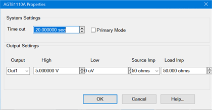
Tip: In the External Device Configuration dialog, you can configure the same 81110A twice; once for each output module. For example:
|
System SettingsTime out - Set the amount of time allowed to communicate with the external pulse generator. If communication has not been established before this amount of time has elapsed, a Timeout message will appear. Check connection settings on the External Device dialog. Primary Mode - When checked, the 81110A trigger mode is set to Internal. This also causes the 81110A to appear as a selection on Integrated Pulse App, Pulse Trigger setting. When selected here and on that dialog, the timing of configured 'follower' pulse generators is controlled by the 81110A pulse generator. Although more than one configured pulse generator can have the Primary Mode setting checked, only one pulse generator can be connected to the rear-panel Pulse connections. Learn more about making physical connections. When this setting is cleared, the 81110A trigger mode is set to External and can be configured as a 'follower' pulse generator to the VNA internal pulse generators or another external pulse generator. Output SettingsThe following are 81110A settings made by the VNA. Some settings may not be possible depending on the modules that are installed on the 81110A. Please refer to the 81110A Quick Start Guide for more information. Output - Select an output on the 81110A. High/Low - Set the pulse voltage levels at the 81110A output. Src Imp (Source Impedance) - Source impedance of the pulse generator output. Load Imp (Load Impedance) - The load impedance value expected at the pulse generator output.
|
Using External Pulse Generators with the Integrated Pulse App
Once configured, an external pulse generator can be used with the Integrated Pulse App as though it were an internal pulse generator.
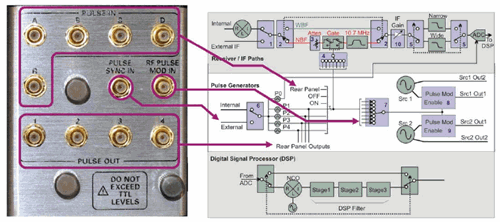
N1966A Pulse I/O Adapter. See an enlarged view of the IF Block diagram

An External Pulse Generators can be used for ONE OR MORE of the following pulsed functions within the Integrated Pulse Application.
Drive the IF (Receiver) Gates (Narrowband mode ONLY).
Trigger the ADC to make receiver measurements (Wideband mode ONLY).
How to Modulate a Source with an External Pulse Generator
When using an external source modulator (Z5623AH81):
Connect: the 8110A to the Z5623AH81 as shown in the Narrowband Pulse topic.
Setting: On the Pulse Generator Setup dialog, disable (clear) the Internal Pulse Modulators .
When using internal source modulators, the external pulse generator can drive the internal modulators in two ways:
81110A directly to the internal pulse modulators.
Connect: 81110A to RF Pulse Mod In on the N1966A OR rear-panel Pulse I/O connector.
Setting: On the Pulse Generator Setup dialog, set Modulator Drive to "External".
81110A drives internal pulse generators, which drives the internal modulator.
Connect: 81110A to Pulse Sync IN, on the N1966A OR rear-panel Pulse I/O connector.
Settings:
On the Pulse Generator Configuration dialog (above) check Primary mode.
On the Pulse Setup dialog, set Pulse Trigger to <ext pulse gen name> .
How to Gate IF Receivers with an External Pulse Generator
(Used ONLY in Narrowband mode.)
When IF Gating is used, the external drive can be routed in two ways:
81110A drives gates directly at the rear-panel IF Gate inputs.
Connect: 81110A to the Pulse IN for one or more VNA receivers on the N1966A OR rear-panel Pulse I/O connector.
Setting: On the Pulse Setup dialog, under Measurement Timing, for the receivers to be gated, set Pulse Gen to <ext pulse gen name>.
81110A drives the internal generators, which drive the gates.
Connect: 81110A to Pulse Sync IN, on the N1966A OR rear-panel Pulse I/O connector.
Settings:
On the Pulse Generator Configuration dialog (above) check Primary mode.
On the Pulse Setup dialog, set Pulse Trigger to <ext pulse gen name>.
On the Pulse Setup dialog, under Measurement Timing, for the receivers to be gated, set Pulse Gen to the internal pulse generator (Pulse0 through Pulse4) to be used to pulse the Rcvr<n>. Set unique pulse Width and Delay for the Receiver.
How to trigger the ADC with an External Pulse Generator
(Used ONLY in Wideband mode).
Pulse0 may be used to trigger the ADC. The following shows how P0 may be driven by an external pulse generator.
Connect: 81110A to Pulse Sync IN, on the N1966A OR rear-panel Pulse I/O connector.
Settings:
On the Pulse Generator Configuration dialog (above) check Primary mode.
On the Pulse Setup dialog, set Pulse Trigger Source to <ext pulse gen name>.
On the Pulse Setup dialog, under Measurement Timing, for the receivers to be triggered, set Pulse Gen to Pulse Trigger. Set Delay for the Receivers.
