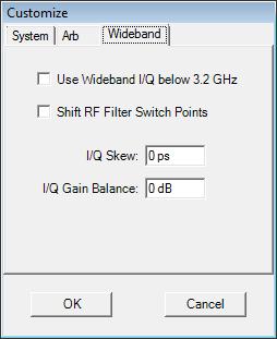
Images are caused by differences in the I and the Q signal paths when using I/Q modulation. One component of the differences is a time skew between the I and Q channel. The skew can be caused by different I and Q cable lengths. The images can be minimized by adjusting the cable lengths or by using the I/Q Skew adjustment on the Wideband tab of the Download > Customize... dialog. This adjustment is real time and available for all Arbs except M9330A/N6030A/N8241A. For these Arbs, adjust the skew by swapping cables or by adding some extra connectors to one cable or the other.
Corrections are not required for this procedure and must be disabled. The other component is I and Q gain imbalance. This is where the amplitude of the I and Q signal paths is different. The I/Q gain balance can be adjusted for all Arbs using the I/Q Gain Balance adjustment on the Wideband tab of the Download > Customize... dialog.
The following procedure was done using an External I/Q configuration and an Keysight Technologies PSA Series Spectrum Analyzer. It is used to match the time length of the I and Q signal paths. Following this process will help the correction measurement achieve its best results. This procedure only needs to be done when the I/Q signal paths have changed significantly. It should be done at least once after the initial system is configured. It is done by viewing a simple test signal on the analyzer while physically changing the I and Q signal paths. Matching the I/Q signal path lengths is applicable when using either the internal base band generator (Options 001, 002, 601, 602), or the external N603xA/M933xA AWG. (There is a frequency band switch point at 3.2 GHz in the E8267C/D PSG Signal Generator. As a result, there are two different I/Q signal paths; one path for frequencies below 3.2 GHz and one path for frequencies 3.2 GHz and above). Optimize the I/Q signal path for the frequency range of most interest.
This process is not necessary for the E8267D PSG, N5182B MXG, N5172B EXG, and E4438C ESG when using the internal AWG. These instruments receive a factory calibration to minimize the I/Q skew.
Use the following steps to minimize the I/Q skew for the N603xA/M933xA AWG, or other PSG/MXG/EXG/ESG signal generators not listed in the note above.
Start the N7620B software and select the desired configuration (Wideband I/Q, External I/Q, or Internal I/Q).
Create a new Pattern. Use the New menu or use the tool bar. The Pattern Details are used by the Test Signal.
Use the Pattern Detail default values and set the RF frequency as desired.
Disable Corrections. Make sure Enable Corrections is not checked on the Download menu.
Set up the analyzer to view the test signal.
Adjust the I/Q signal paths while viewing the analyzer to minimize the images. Matching the internal I/Q signal paths is accomplished using the I/Q skew Adjustment in the I/Q Adjustment menu on E8267C/D PSG.
This skew value may be different for frequencies above 3.2 GHz. Matching the external I and Q signal paths for the N603xA/M933xA AWG is accomplished by substituting cables, adding some BNC connectors to the signal path, or both.
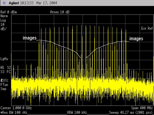
The following figure illustrates a test signal for an external I/Q configuration.
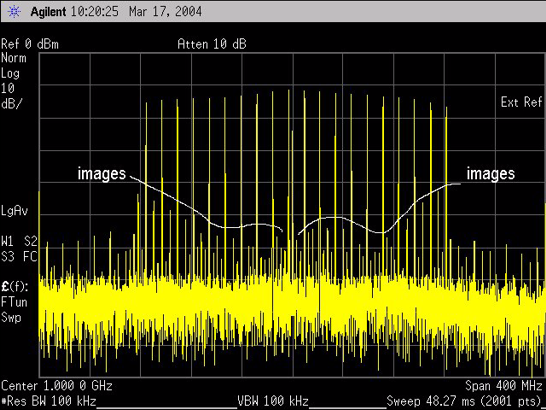
The following figure illustrates the same signal after the I and Q signal paths have been adjusted using BNC connectors.