This topic applies to NA520xA PNA-X Pro models only.
In this topic:
See also:
NA520xA PNA-X Pro models modify the Noise Figure Setup dialog. Instruments with dedicated noise hardware will provide four gain settings while instruments without dedicated noise hardware will provide two gain settings.
|
Question |
Answer |
|---|---|
|
Are the SCPI commands compatible with legacy models? |
With dedicated hardware, the gain settings are similar to the legacy settings (30 dB, 15 dB, 0 dB, and -15 dB). Without hardware, NF now has two gain settings (0 dB and -15 dB). |
|
Is the GUI compatible with legacy models? |
The GUI looks nearly the same, however, the NF gain settings are very different. See above. |
|
How do I switch between dedicated NF hardware and VNA? |
The source path mechanical "NF Switch" determines whether the noise hardware is being enabled. Setting the receive-side switch to "Noise Path" will enable all four gains for NF measurements; setting it to "Thru Path" will disable the highest two gain settings. Setting the source-side switch to "Noise Path" will enable NF tuner corrections. If NF hardware is not available, these switches cannot be set. |
|
Can I view receiver settings used for NF? |
Yes. The "RF/LO/IF Path Config" dialog displays settings used for S-parameter measurements. The new "View NF Path" dialog displays the settings used for noise measurements. This new dialog is opened from the NF Setup dialog. |
|
Are there any frequency limitations? |
Yes. In NF Gain settings 0 dB and -15 dB, the couplers are used which begin rolloff at 700 MHz and have an additional 36 dB loss at 10 MHz. Measurements at 10 MHz are likely unusable. |
|
Using Hardkey/SoftTab/Softkey |
Using Menus: |
|
|
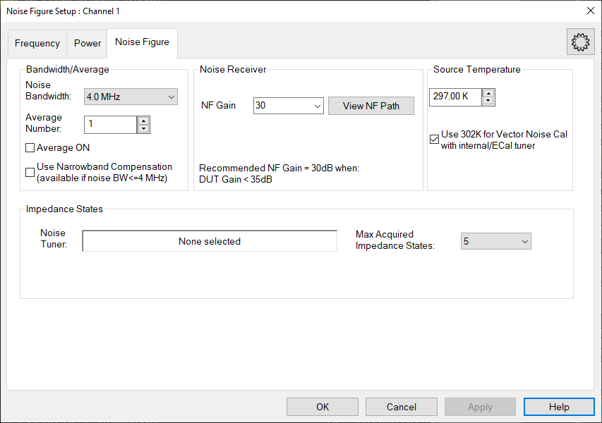
This mode is enabled by setting the "NF Switch" behind the Test Coupler to the "Noise Path".
If the hardware option is available, then the NF hardware is enabled by default.
The NF Gain is set to 30 dB by default.
The available NF Gain settings are: 30, 15, 0, and -15 dB.
If the NR1 hardware option exists, then these settings can also be made on Port 2. If the NR1 hardware option exists, default behavior is still to use Port 2 as the output port.
See the View NF Path dialog for more information about the settings.
This mode is enabled by setting the "NF Switch" behind the Test Coupler to the "Thru Path". If there is no "NF Switch," then this is the only mode.
The NF Gain is set to 0 dB by default.
The available NF Gain settings are: 0 and -15 dB.
See the View NF Path dialog for more information about the settings.
"View NF Path..." Button: Opens the View NF Path dialog, displaying settings of the NF path.
When a "NF Gain" value is selected from the combo-box, the readout will indicate the recommended gain range of the DUT.
This value is calculated by determining the total noise power which will cause P0.1dB compression in the receiver.
|
NF Option |
NF Gain |
Recommended DUT (Gain+NF) |
|---|---|---|
|
Dedicated NF Hardware |
30 dB |
< 35 dB |
|
15 dB |
25 dB ~ 45 dB |
|
|
0 dB |
35 dB ~ 55 dB |
|
|
-15 dB |
> 45 dB |
|
|
VNA |
0 dB |
< 50 dB |
|
-15 dB |
> 40 dB |
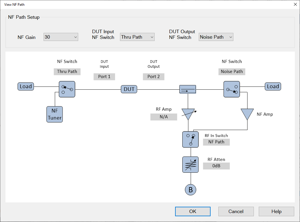
The switch settings on this dialog are used for the NF measurement, not for the S-Parameters. If the user opens the RF/LO/IF Path Config dialog, the settings displayed on the Receiver tab will describe the path settings used during the S-parameter measurements; they may not match the settings displayed in the View NF Path dialog.
This gain is the same value as selected on the NF Setup dialog.
The "DUT Output NF Switch" setting affects the choices in this combo-box.
If set to "Noise Path," then the user may select 30, 15, 0, and -15 dB.
If set to "Thru Path" or if there is not switch, then the user may select 0 and -15 dB.
This may be: Noise Path, Thru Path.
The NF App will set this to "Noise Path" by default if it is available.
When in the "Noise Path" position, the NF App may use the Noise Tuner during NF measurements.
The user may set this switch from this dialog or the RF/LO/IF Path Config dialog. This is a mechanical switch, so its setting will be used for both NF and S-Parameter measurements.
This may be: Noise Path, Thru Path.
The NF App will set this to "Noise Path" by default if it is available.
When in the "Noise Path" position, there are four available gain states, otherwise there are only two available gain states.
The user may set this switch from this dialog or the "RF/LO/IF Path Config" dialog. This is a mechanical switch, so its setting will be used for both NF and S-Parameter measurements.