This topic applies to NA520xA PNA-X Pro models only.
In this topic:
See also:
|
Using Hardkey/SoftTab/Softkey |
Using Menus: |
|
|
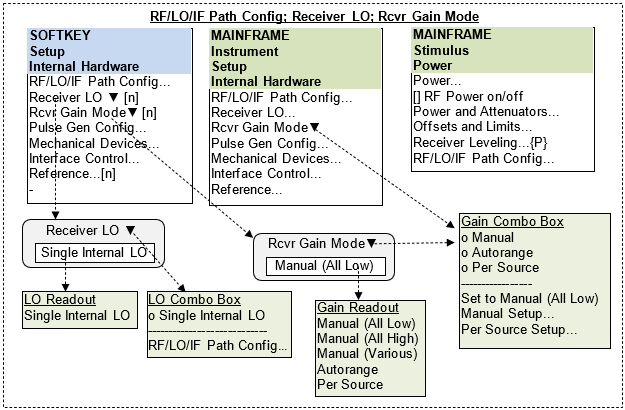
Default state is "Manual (All Low)".
Combo box:
You may choose one of three gain modes: Manual, Autorange, Per Source.
"Manual Setup..." opens the "RF/LO/IF Path Config" dialog on the "Receiver" tab.
"Per Source Setup..." opens the Gain Per Source Setup dialog.
"Set to Manual (All Low)" sets the manual gain mode with all receivers low.
Softkey readout pane
Will display one of five possible labels.
If it's in Manual mode, it will display either "Manual (All Low)", "Manual (All High)", or "Manual (Various)" depending on the state of the receiver RF Amp settings.
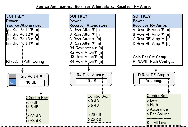
The mode switch toggles between Manual and Auto. Default is Auto.
Selecting an attenuation value from the combo box will disable Auto mode.
If the Port Powers are Coupled, then the Source Attenuators are coupled.
The readout indicates the units "dB".
Default settings are 0 dB for test receiver and 5 dB for reference receivers.
Receiver attenuators are not coupled.
The readout indicates the units "dB".
Default setting is Low.
If Autorange is selected, then all amps are set to Autorange.
If Per Source is selected, then all amps are set to Per Source.
The "Per Source Setup..." button opens the Gain Per Source Setup dialog for setting the Per Source values.
The "RF/LO/IF Path Config..." button opens that dialog on the "Receiver" tab.
The diagram below shows all four sources and four ports of the VNA.
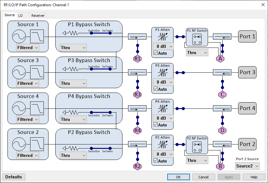
Changing the combo box changes the picture in this block.
There are two choices:
"Filtered" - filters the low band of the source.
"Hi Pwr" - Bypasses the low band filters, resulting in higher power.
Changing the combo box changes the picture in this block.
There are three choices:
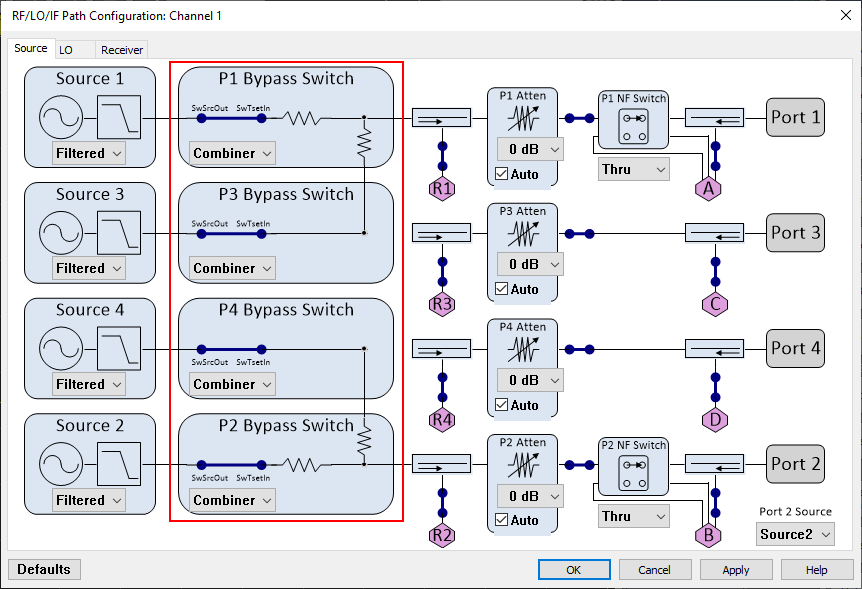
"Combiner" - For ports 1 and 2, this routes the signal through the jumper, then through the combiner, then to the test port. For ports 3 and 4, this routes the signal through the jumper, then to the combiner on either port 1 or port 2. (See figure below.)
"Thru" - this is a straight thru to the front panel. Note that ports 3 and 4 also show the jumper which is connected to the combiner in the other port; this allows you to route an external source to the combiner while still using the internal VNA source.
"Jumper" - this is the straight thru to the front panel but runs the signal through the jumper.
Choices: 0 dB, 10 dB, 20 dB, 30 dB, 40 dB, 50 dB, 60 dB
"Auto" checkbox allows user to place in auto mode
This block represents the mechanical switch between the two couplers.
Changing the combo box changes the picture in this block.
There are two choices:
"Thru Path" - Routes the source directly to the port.
"Noise Path" - Routes the test receiver directly to the port.
You may select: Source 2, Source 3, Source 4.
This provides backwards compatibility with legacy PNAs.
Selecting a source does not change any switches; it just indicates a mechanical connection between jumpers in the diagram.
Default is Source 2.
If Source 3 is selected, then
P2 Bypass Switch will indicate Jumper is disconnected
P3 Bypass Switch will indicate Jumper is disconnected
A line will be drawn from P2 Bypass Switch "SwTsetIn" node to P3 Bypass Switch "SwSrcOut" node
If Source 4 is selected, then
P2 Bypass Switch will indicate Jumper is disconnected
P4 Bypass Switch will indicate Jumper is disconnected
A line will be drawn from P2 Bypass Switch "SwTsetIn" node to P4 Bypass Switch "SwSrcOut" node
NOTE: The Sources are always labeled as "Source 1", "Source 2", "Source 3" and "Source 4" even if the VNA is optioned as a 1-source or a 2-source VNA. These options only indicate the number of sources which can be turned on at the same time, and do not affect the source numbering scheme.
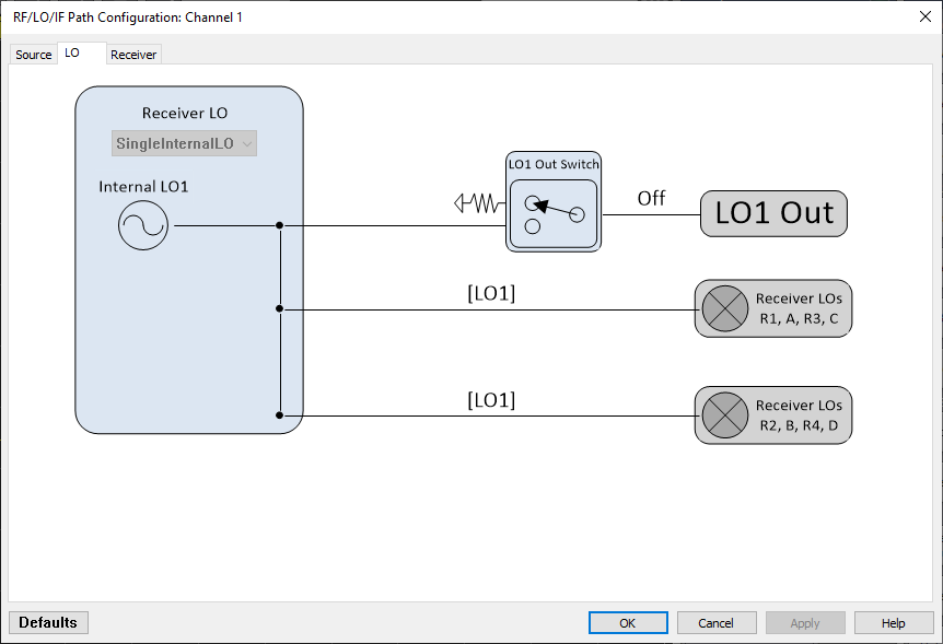
Combo Box Choices:
"Single Internal LO"
Changing the combo box will redraw the diagram in the block and change labels.
Default is "Single Internal LO".
Clicking on switch turns LO1 output on/off
Label on the connector indicates [LO1], [Off]
Default = Off
LO1 output power is 6 dBm nominal and cannot be adjusted by the user
Pressing the "Defaults" button will set: Receiver LO = Single Internal LO
Readout
May display: Low, High, Autorange, or Per Source
If one amp is set to Autorange, then all are set to Autorange.
If one amp is set to Per Source, then all are set to Per Source.
Default is Low
Combo box
Allows the user to select: Low, High, Autorange, Per Source
Selecting "Per Source" will not open the "Receiver Gain" dialog
Default = Low
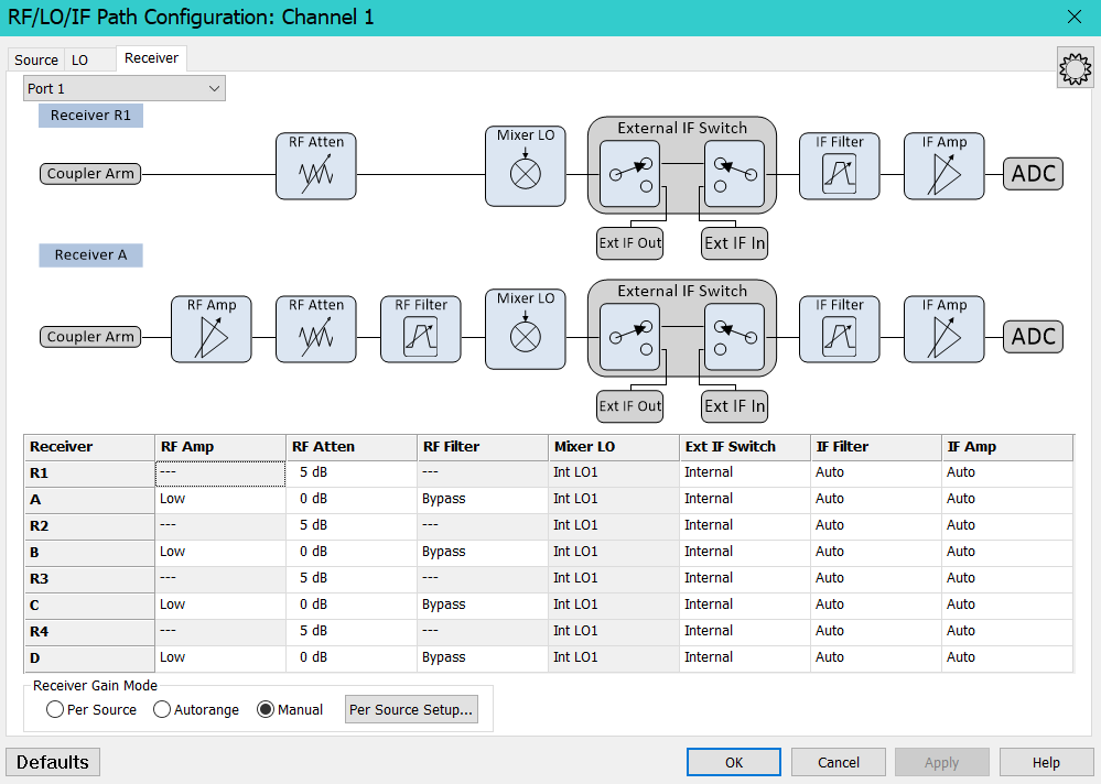
Choices: Low, High
The NF Amp will only use "Low" for frequencies below 7 GHz because the high-frequency performance of this path is limited.
Reference receivers have no switch so indicate "-" in table.
Choices: Coupler Arm, Noise Path
"Coupler Arm" is default. This connects the receiver to the test coupler arm.
"Noise Path" connects the receiver to the noise figure circuits.
NOTE: If you set the source NF switch to Noise Path and set the RF In Switch to Coupler Arm, then the NF receiver solid state switch will route the RF source to the test port.
Attenuator may be set from 0 dB to 25 dB in 5 dB steps using the combo box.
Default = 0 dB for test receivers, 5 dB for reference receivers.
The RF Amp setting does not affect the RF Atten setting.
Choices are, in this order: Auto, Tracking, Bypass, (list of filters).
The default setting depends on the application.
"Auto" is only available for the NF application. It is not displayed for other measurement classes. NF will measure S-parameters and noise on alternate sweeps, so the filter is constantly changing.
"Tracking" forces receiver to always use the filters, but to automatically select the appropriate filter depending on the frequency being measured. This might be used for S-parameters or other measurements that normally don't use the filters. It also allows the user to configure the system for specialized measurements which may require the filter path, but the user doesn't want to set the filters by hand for each frequency measurement.
This is a read-only column. It will display selections from the LO tab.
Possible text for Receiver A, C, R1, R3: Int LO1, Not Used
Possible text for Receiver B, D, R2, R4: Int LO1, Not Used
Choices:
"Internal" is the default. The signal is routed from the internal mixer to the IF.
"External" will route the mixer IF out to the rear panel IF out connector and will route the rear panel IF In connector to the IF path.
Choices: Auto, Wide, Narrow
Default: Auto
Choices: Auto, 0 dB, 2 dB, 4 dB, 6 dB, 8 dB, 10 dB, 12 dB, 14 dB
"Auto" = default setting. The VNA will choose the value it deems appropriate given the frequency and measurement.
"Per Source" radio button: Selecting this will set all RF Amps to the "Per Source" state. This has no effect on the RF Atten settings. Selecting this radio button will not automatically open the Gain Per Source Setup dialog. You must select the "Per Source Setup" button to open that dialog (described below).
"Manual" radio button: Selecting this will allow the user to manually set the RF Amp. This is enabled by default. When switching from Per Source to Manual, the RF Amps will return to their previous settings.
"Autorange" radio button: Selecting this will set all RF amps to Autorange mode. This has no effect on the RF Atten settings.
"Per Source Setup..." button: Applies and closes this dialog, then opens the Gain Per Source Setup dialog. If Receiver Gain is in Manual mode or Autorange, the mode will not be automatically switched to Per Source mode.