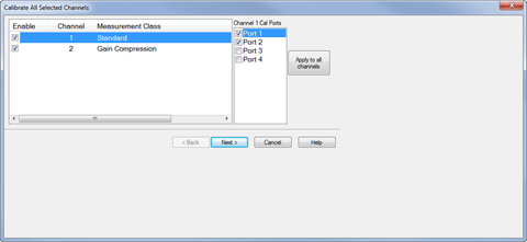
The procedure in this topic describes how to perform a calibration using the Cal All Calibration Wizard method, which allows multiple channel calibration in a single session.
Calibration procedures accessed in the user interface vary depending on which application (Measurement Class) is active. For information about other calibration methods and their purpose, refer to the following links:
A power table can be used instead of multiple power sensors to cover a wide frequency range. In addition, a power table can be used when the measurement frequency exceeds the frequency range of the power sensor (typically > 110 GHz). Refer to Creating a Power Table for information on how to create a power table.
Ensure that the measurement classes to calibrate are active.
Press Cal > Main > Other Cals > Cal All... to launch the following dialog showing the active measurement classes:
Check the measurement classes to calibrate.
Select the ports, then click on the Apply to all channels button to apply the port selections to all channels.
Click Next, then confirm or change the calibration properties in the Measurement Class Cal Properties dialog.
Click Next. to access the Calibration Attenuator Settings dialog.
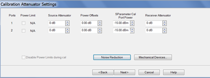
In the Calibration Attenuator Settings dialog, perform the following:
Set the attenuator settings. Learn more.
Click on the Noise Reduction button to improve measurement accuracy. Learn more.
Click on the Mechanical Devices button to view all switches and attenuators in the VNA. Learn more.
Click Next, then select the DUT connectors and calibration kits in the Select DUT Connectors and Cal Kits dialog.
.Click Next to access the Power Cal Settings dialog.
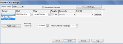
In the Power Cal Settings dialog, perform the following:
Check Use Multiple Sensors if more than one power sensor is needed to cover the frequency range then select a sensor from the Sensor down menu.
Otherwise, check Use Multiple Sensors then select the power table from the Sensor drop down menu. Learn how to create a power table.
Learn more about Accuracy Tolerance and Max Number of Readings.
Click Next and follow the calibration process until completed.
A power table is a text file with data that describes the output power of the module as a function of frequency. This is valid when the frequency extender module is driven at high levels (+11 dBm). This file may have been created for you by a third party or shipped with your frequency extender Module. If not, you can create this *.prn file from the manufacturer's specification for the frequency extender module.
This file can be created manually, using a text file program such as Notepad.
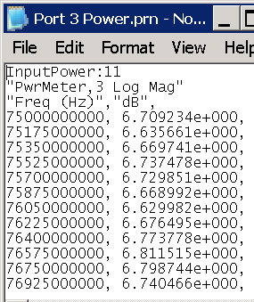
Example .prn file
C:\ProgramData\Keysight\Network Analyzer\Configurations\<configuration name>\
where configuration name is a directory name that is also the name of the currently selected configuration in the Millimeter Configuration dialog. For example, "N5291A Broadband".