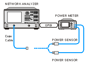
|
Note: Be sure that the frequency range of your power sensor covers the frequency range of your measurement. This does NOT occur automatically.
Channel and Port Selection
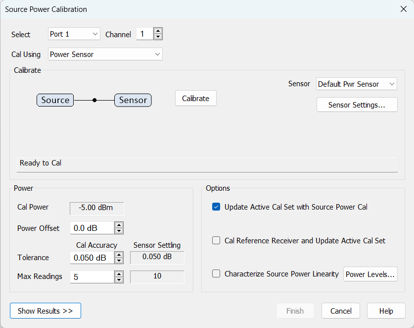
Channel Specifies the channel on which to perform the calibration. This setting defaults to the active channel.
Source Port Specifies the source port to be corrected. This setting defaults to the source port for the active measurement.
Note: External sources can be calibrated using this dialog. Learn more.
Calibration Reference Choose power meter/VNA receiver to use to measure power.
Note: Because the following two settings use VNA receivers to make power measurements, they do NOT work correctly when a Frequency Offset value is being used.
-
Cal Using Sensor + Receiver. When checked, the first reading at each data point uses a power meter to calibrate the reference receiver. Subsequent readings, if necessary to meet your accuracy requirement, are measured using the reference receiver. This technique is much faster than using the power meter, and more accurate when measuring low power levels.
Note: Do NOT use this setting if there is a component before the power sensor that exhibits non-linear behavior, such as a power amplifier in compression. Use a power meter and Calibrate the source at multiple power levels.
Buttons
Sensor Name All power sensors are displayed in this menu even if "Active - Show in UI" has been disabled in the External Devices setup dialog. You can select "Add Sensor..." to open the External Device Configuration dialog to the power meters page and configure more sensors. If you have pressed the "Options" button and selected "Receiver Only" or "Source Power Table", then this menu displays "None" and contains no entries.
Note: Default Sensor Auto-Switching. This feature is only available for Source Power Cal and SMC Smart Cal (GUI or SCPI) when the "Enable Frequency Checking" checkbox is selected. It automatically switches the sensor channel (A - B - C - D) when the calibration frequency is out of range for the current sensor channel's specified frequency range. See also, Enable Frequency Checking.
Sensor Settings Opens the Configure Power Sensor dialog for the currently selected power sensor.
Calibrate Begins source power calibration measurement.This button becomes "Abort Cal" during calibration and clears the current calibration data and process if pressed.
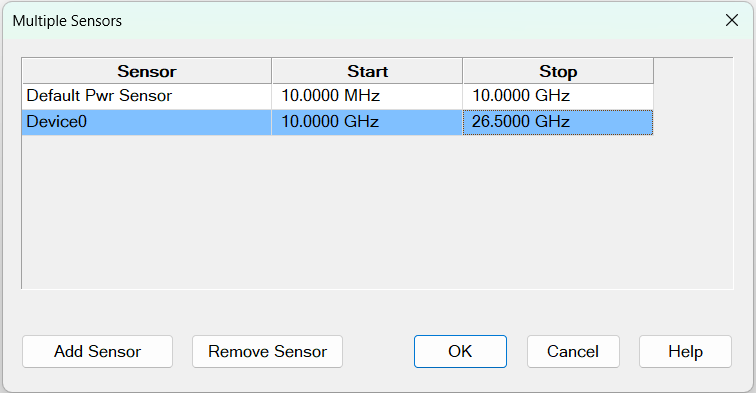
Multiple Sensors... Opens a new dialog box for defining multiple sensors across different frequency ranges. When selected, the readout displays "Multiple Sensors..."
Power
Cal Power The calculated power (in dBm) at the calibration point. This value is the specified VNA source power plus the Power Offset value.
Power Offset Allows you to specify a gain or loss (in dB) to account for components you connect between the source and the reference plane of your measurement. These components will remain during a measurement. For example, specify 10 dB to account for a 10 dB amplifier in the path to your DUT. Following the calibration, the VNA power readouts are adjusted to this value.
To account for components that will be removed when the calibration is complete, use the Loss Compensation table.
Cal Accuracy
At each data point power is measured, then adjusted until the reading is within this Cal Accuracy Tolerance or the Max Number of Readings has been met. The last power reading is plotted on the screen against the Tolerance limit lines.
Tolerance Sets the maximum desired deviation from the specified Cal Power level in 0.005 dB increments from 0 to 5 dB
Max Number of Readings Sets the maximum number of readings to take at each data point for iterating the source power. Enter a value between 1 and 1000.
Sensor Settling
Tolerance This value used for sensor settling. When two successive measurements differ by less than the tolerance value, then the sensor is considered to be settled, and the last measurement is used. If tolerance is set to zero, then rather than testing successive meaurements, the sensor will be measured Max Readings times and the mean of the readings will be returned. The sensor settling tolerance is defined in the Sensor Settings dialog.
Max Readings Maximum number of readings allowed for sensor settling. Default is 10.
Options
Note: At low power levels (less than -30 dBm) most power meters are not as accurate as a VNA receiver.
-
Update Active Cal Set with Source Power Cal Stores the source power correction and timestamps to the active cal set.
-
Cal Reference Receiver and Update Active Cal Set Check to calibrate the appropriate reference receiver to the power level that is measured at the calibration plane. Do this to make very accurate measurements using the calibrated reference receiver. This cal is done in addition to the standard source power cal using the any of the methods listed above. At the end of the source power cal measurement sweep, you can optionally save the reference receiver cal to a Cal Set to be recalled at a later time. The Cal is saved when the Finish button is clicked to close the Source Power Cal dialog.
-
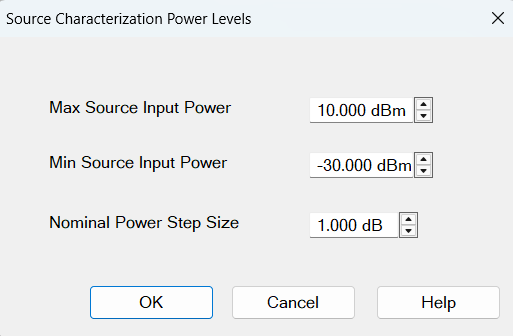
Characterize Source Power Linearity Used primarily with mmWave measurements. This feature can also be used with standard VNA measurements when a component is used in the source path such as a booster amp which does NOT have linear gain or loss over frequency. If this is not true for your setup but want to improve your source power accuracy, consider using the Receiver Leveling feature. When checked, source power is measured using the specified 'Cal Reference' device (power meter/sensor or VNA receiver) and iterated on a sweep-to-sweep basis to construct a 2-dimensional power table: Power IN, Power OUT, over all frequencies.
-
Click Power Levels to launch the Source Cal Power Levels dialog box to set the power levels at which source power is to be measured.
-
The source power cal is saved, but the power table is NOT accessible.
Source Power Cal Frequency Extenders
An uncalibrated frequency extender is inherently nonlinear. To compensate for this, the VNA provides two levels of calibration.
• Source Linearity Cal This first level cal creates a Pin/Pout table to provide a linear, controllable output power level.
• Source Power Cal This second level cal adjusts the output power to match the requested target power.
Recommendation: the preferred method for calibrating a frequency extender starts with an installation cal launched from the Millimeter Configuration dialog.
The installation cal will create a PIn/Pout table that will survive power cycles and will be associated with a specific millimeter configuration. This calibration is often referred to as the source linearity cal.
Source Power Cal dialog This calibration behaves differently depending on the presence of a source-linearity cal created by the installation cal.
With an Installation Cal:
When an installation cal is present the extender output power can be controlled in a reasonable manner. To verify linear control, do this:
1. Create a channel
2. Measure the receiver on the port where the extender is connected. (eg: a1,1)
3. Sweep the channel
4. Normalize the reference receiver trace
5. Now adjust the power in x db steps
6. The trace should move by approximately x dB.
To achieve more accurate port power, a 2nd level source power calibration should be performed. This can be done in the Source Cal Dialog.
Power Calibration Reference The reference for this calibration can be either a power sensor or a Source PMax table.
Source PMax Table A Source PMax Table is generally provided by the manufacturer of the extender. The data in the table represents the maximum output power available from the extender when the device is driven into saturation. The RF input power required to achieve saturation depends on the specific device and typically ranges from +2 to +12 dBm. The Source PMax table file indicates the RF input power used to acquire the table. See the Input Power line at the top of the file. Also note that the RF Input Power to the head is limited by the setting for "RF Max Power In" defined by the Millimeter configuration dialog.
When a Source PMax table is used as the reference, the head will temporarily be driven into saturation. The VNA's reference receiver is then corrected to report the output power levels indicated by the table. The VNA reference receiver is then used to measure the extender output power and produce an offset correction array.
When a sensor is used instead of a Source PMax table, a similar sequence is executed except that the VNA measures the extender output power using the sensor and transfers the result to the VNA reference receiver. Then the cal proceeds to servo power to the desired level and produce an offset cal while using the VNA receiver to measure the power.
Note: Unlike the Source Linearity cal, the results of this 2nd tier cal reside in the channel. It is volatile.
Without an Installation Cal If no installation cal is present, the source power cal dialog can still be used to calibrate the extender. However this calibration will take longer because it must perform both a Source Linearity cal and a Source Power cal. It may also produce a less accurate result.This calibration can be done with either a power table or a sensor. Using a sensor will be slow.
The calibration starts out at saturated levels and will show the available output power on the display. It will then loop through a long series of sweeps, dropping the input RF power to the head to acquire a PIn/POut table. This table is used to linearize the source power. The second part of the calibration will calibrate the source output power at the currently set power level. Depending on point density, some points in the sweep may fall outside the limit lines.
This entire calibration is scoped to the active channel and will be destroyed when the channel is deleted. (See above recommendation.)
Important
1.Check your port power level setting before starting this calibration! On units with no linearity cal, the default power level is usually +10 dBm. It's likely that this extender output power level cannot be achieved across the entire range of the extender. You must set the channel power below the lowest point of the maximum output power curve for the frequency range being calibrated. If the requested channel power is higher than what the extender can output across the x-axis range, then the calibration will fail.
2.The calibration will loop over a range of Extender input RF powers. The input power range may be adjusted by pressing the "Power Levels..." button and editing the table on that dialog.
Warnings
Calibration Warning Dialog:
If a power cal is going to be performed on a source which has the RF Pulse Modulator enabled, a warning dialog is displayed when you click Calibrate.
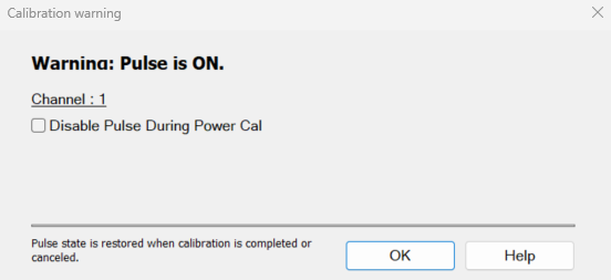
Disable Pulse During Power Cal Select the checkbox to disable the RF Pulse Modulator on the source being calibrated during the power cal only and will be re-enabled after the power cal.
For Noise Figure calibrations using a noise source, the Disable Pulse during Power Cal warning can be ignored.
If the channel is NFX with a controlled LO signal that is being modulated, and the LO is being power calibrated, the pulse warning should be considered.
Finish Applies calibration to all ports that have been calibrated. This button is disabled until there's a completed calibration on any port.
Cancel If a sweep is in progress, cancels the sweep. Press again to close the dialog.
Attention please: the power meter is operating in 200 r/s mode.
During a measurement, some Keysight power meters may display this message on the screen: It means that the meter is operating in 200 readings/sec which is the fastest speed setting for this meter. This is normal operation.
Frequency Checking Error Dialog:
If frequency checking has been enabled, then the VNA will check that the power sensors are defined over the calibration frequency range. If not, then this error dialog (see below) is displayed when you click the Calibrate button or, in the case of a Guided Power Calibration, the Next button.Frequency Checking is enabled in the Sensor Settings dialog.
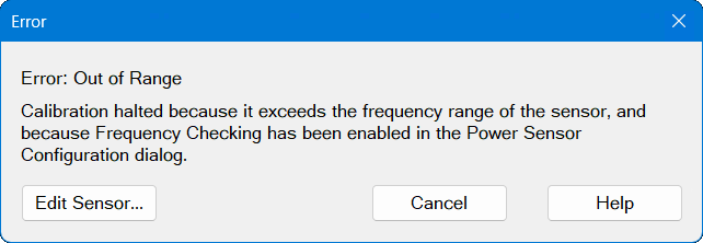
Edit Sensor... Opens the "Configure Power Sensor" dialog for the selected sensor. The sensor I/O is connected automatically so the dialog displays all the settings and controls, rather than just showing the "Sensor Settings..." button. From this page, you can change the sensor settings. Clicking OK returns you directly to the Source Power Cal dialog.
Cancel Closes this dialog and returns you to the Source Power Cal dialog.
Pass / Fail Limits
Limit lines are drawn on the Source Power Cal measurement graticule area. These lines are at the Cal Power +/- the current setting of Accuracy Tolerance. A FAIL during the Source Power Cal sweep means that the VNA was unable to measure power to within the Accuracy Tolerance. Tight tolerances are more difficult to achieve at lower Cal Power levels. When a FAIL indication appears, increase the Max Number of Readings. If this does not cause a PASS condition, then decrease the Accuracy Tolerance value.
See Also
|
 and are controlled by the VNA exactly like a USB sensor. See USB Power Sensors (above). Although these meters may also have a front-panel USB port, USB sensors placed on these ports can only be accessed via SCPI. Otherwise, connect USB power sensors directly to one of the VNA USB ports.