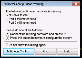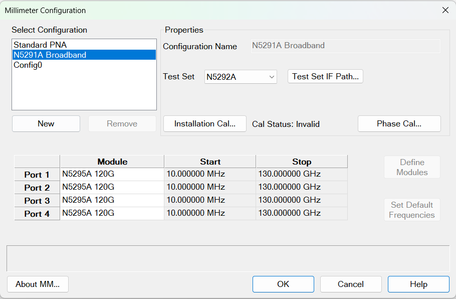
Select Configuration Lists the Standard VNA configuration, N5290A Broadband, N5291A Broadband, and other configurations that you have created.
-
Click New to create a new Millimeter Module configuration. A name is automatically selected. Edit the Configuration Name field to change it.
-
Click Remove to delete the selected configuration.
-
Select N5290A Broadband or N5291A Broadband millimeter-wave systems.
-
For banded, define a frequency band.
-
Select Standard PNA to exit the Millimeter mode to use the analyzer as a standard VNA.
Properties
Configuration Name Shows the currently selected configuration. Edit this field to change the configuration name. Type a unique name using only alphanumeric and underscore characters. Only custom configurations can edit this field.
Test Set Select a test set to use in the current configuration. The firmware verifies that the selected test set is connected. If the selection does not match the connected test set, an error message is displayed. However, you are not prevented from continuing.
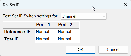
Test Set IF Path... Route the Reference or Test IF to the front panel (Front) or rear panel (Normal) of the test set. The rear panel connector limits the IF to less than 40 MHz while the front panel connector limits the IF to less than 2 GHz. Each port has a Reference IF and a Test IF switch. Each IF switch is independent per port and per channel. At preset, the default is Normal. IF switch settings are saved with the instrument state.
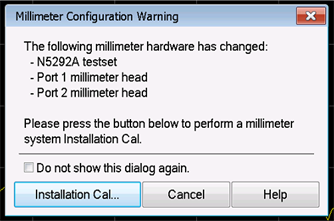
Installation Cal... The installation calibration adjusts the source power at the output of the frequency extender. It also adjusts for IF path loss variation. These can change each time a frequency extender is moved from one port to another or from one system to another. Perform this calibration each time a change is made to the configuration. For a procedure, refer to Installation Cal.
| Cal Status | Description |
| Complete | All cals are done, including optional cals if available. |
| Valid | All required cals are done. Optional cals may not be done. |
| Invalid | The required cals are not done. |
Phase Cal Launches the phase calibration procedure. These calibrations are only required for wideband modulation measurements. They have no impact on other measurements. An IF Response cal is required before the phase cal.
Module Grid
Module Assign a module to each VNA port. Clicking on a cell in this column displays a combo box with all available modules. Module definitions can be created via the Define Modules button. Keysight frequency extenders are automatically detected and populated in N529xA Broadband configurations.
Start and Stop Frequency Set the Start and Stop frequencies of the modules in the selected configuration. These are limited by the module frequencies set in the Module Setup dialog.
Set Default Frequencies (Custom configurations only) Resets the module frequencies to preset default values.
2-Tone Head Connected to P1 and P3, w/ P1 = Rcvr Used to indicate that there is a dual-source banded module connected to Port 1 and Port 3. This setting requires that Port 1 and Port 3 are assigned to the same module in the grid.
Define Modules
(Custom configurations only) Opens the Module Setup dialog where you can create, copy, edit, or remove custom module definitions.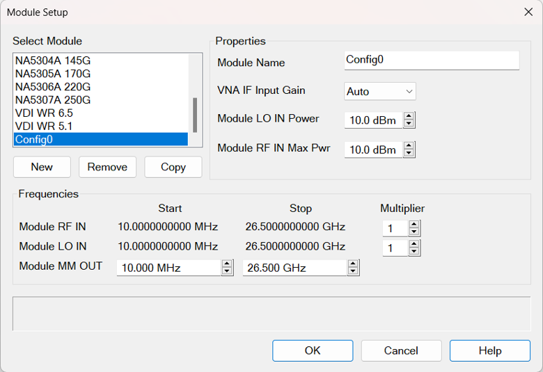
Module Properties:
Module Name A unique name for the custom module.
VNA IF Input Gain When Auto is selected, the IF gain is automatically adjusted depending on the frequency of operation to avoid overdriving the receivers. The IF gain can also be manually selected from a list of values depending on the hardware.
Module LO IN Power Sets the LO drive power to the module.
Module RF IN Max Pwr Defines the maximum RF drive power to the module. After the millimeter configuration is applied, set the power out of the MM output port using the Power and Attenuator dialog.
Module RF IN This row displays the module's RF input frequency range (read only) which will be multiplied by the multiplier value to generate the millimeter output frequencies.
Module LO IN This row displays the module's LO input frequency range (read only) which will be multiplied by the multiplier value to generate the receiver's LO millimeter frequency.
Module MM Out This row display's the module's millimeter frequency range.
OK Closes the dialog. Saves the configuration and presets the VNA before applying the appropriate settings.
Cancel Closes dialog box without saving changes.
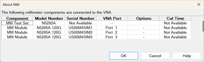
About MM... Displays information about the current hardware configuration.