Installation Cal
This topic describes how to perform an Installation Cal for N5290A/N5291A Broadband systems or for Banded systems (VDI), which should be done each time a change is made to the configuration.
-
Installation Source Calibration
-
This process allows us to characterize the raw source power of each module by varying the power to the module and measuring the response over frequency using the reference receiver.
-
During this process we create a 2-D power table that would be used when we want to set the power at the port of the module.
-
User Source Power Calibration
-
This is only done prior to making a measurement that requires an accurate power at the measurement port, which could be the module test port or the end of a cable or adapter.
-
Generally is a single sweep measurement at the required power, and uses the Installation power calibration to adjust the power for different power levels.
-
IF Flatness calibration
-
For this process we require that the module do not have anything attached
-
In this case we adjust the IF loss from the receiver in the module to the IF input at the rear of the PNA-X
-
It also matches the IF to that of the internal DAC range.
Note: The Installation Cal must be performed before the Smart Cal procedure.
In this topic:
Installation Cal - N5290A/N5291A
-
An installation cal is strongly suggested.
-
The Installation Calibration should be performed each time a change is made to the physical configuration, i.e. a cable change, a change in millimeter head, or a PXI module change.
-
The Installation Calibration characterizes the input/output power relationship for each millimeter module.
-
The Installation Calibration results in a +/- 5 dB source power calibration.
-
The Installation Calibration provides an approximate VNA receiver calibration. It does NOT provide any calibration of the VNA receivers.
-
The Installation Calibration is applied system wide. It can be enabled and disabled, but only on a system wide basis. It cannot be enabled or disabled on a channel by channel basis.
-
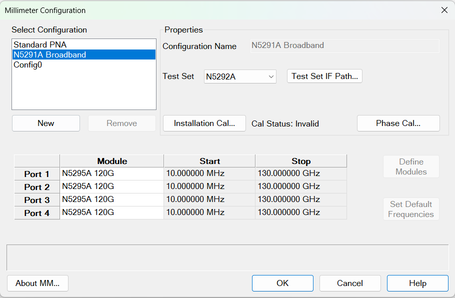
Press Setup > External Hardware > Millimeter Config. The Millimeter Configuration dialog is displayed.
-
Select the N5290A Broadband or N5291A Broadband configuration.. For information on creating a millimeter configuration, refer to the Millimeter Configuration Dialog help.
-
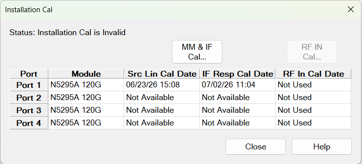
Click on the Installation Cal... button to enable the configuration and launch the calibration. The following dialog is displayed. This dialog displays the calibration date for each port if calibration was previously performed. Otherwise, "Not Available" will be shown in the Cal Date column. Cals that are not necessary will show "Not Used" in the Cal Date column.
-
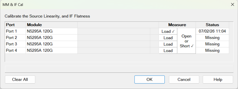
Click on MM & IF Cal...
-
Connect a waveguide load to Port N.
-
Click Load under the Measure column to run the source linearity calibration on the port connected to the load. RF In power is swept while measuring the MM output power using the reference receiver.
-
Repeat steps 5-6 until all ports are calibrated.
-
Connect an Open or Short standard on all ports.
-
Click Open or Short to perform IF Flatness calibration on all ports.
Clear All Deletes all cal files from the active configuration.
Installation Cal Banded
The following describes the process for the installation and calibration when using banded 3rd party frequency extenders with a PNA/PNA-X that is connected via a N5292A test controller.
This is to ensure that when the N5290/91A broadband is used with the N5290A304 1.8m cable adapter the system is optimized for the best power levels being applied to the RF and LO of the external modules. In addition, it will ensure that we have a calibrated IF channel for accurate raw receiver measurements that require this level of accuracy, like the Spectrum Analysis application.
Note that the above calibration and installation process optimized for use with supported VDI and OML frequency extenders. While other Frequency extenders may be used, they should at minimum comply with the requirements as follows:
-
Nominal RF saturated power requirement of 10 dBm +/- 4 dBm. (9.2GHz-21.3GHz).
-
Nominal LO saturated power requirement of 10 dBm +/- 3 dBm. (9.2GHz-21.3GHz).
-
The IF level should be optimized for an operation of 7.606 MHz and not exceed the -20 dBm.
System Hardware
In the description we will use the following hardware:
- N5242B
- N5292A Test Set Controller
- WR-10 3rd party frequency extenders
Required Calibration Hardware
The process would require at least a 26.5 GHz power sensor and adapter to complete.
Overall Process
- Connect the PNA-X, controller and attach the N5290A304 cable adapters
- Do not connect the frequency extenders to the N5290304A cable adapters
- Connect the power sensor to the PNA-X
- Configure the power sensor for measurements
- Use the millimeter Wave Configuration Dialog to configure the modules.
- Select the installation menu to start the calibration of the system
- Complete the calibration steps, for optimal performance all steps should be completed.
Procedure
1. Press Setup > External Hardware > Millimeter Config. The Millimeter Configuration dialog is displayed.
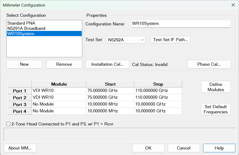
2.Select an existing Banded configuration or create a configuration by clicking New. In this example, the configuration is named "WR10System".
3. Click on Define Modules button and define the VDI WR10 module.
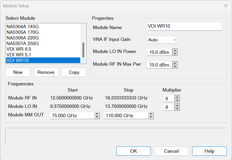
4. Click OK to save this module configuration.
5. Assign VDI WR10 to Port 1 and Port 2.
6. Assign Test Set to be a N5292A.
7. Click the Installation Cal... button. The Banded Installation Menu dialog appears.
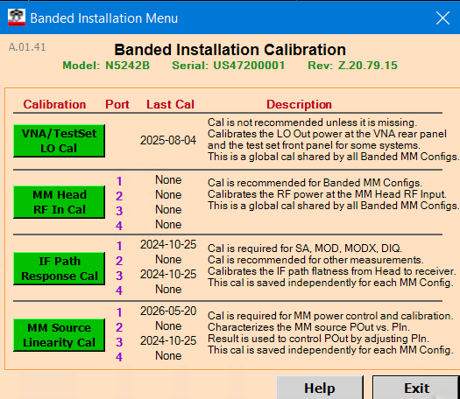
8. The 4 Cals should run in the order shown: LO first, RF second, IF third, MM source linearity fourth. (Calibrations described below)
LO Calibration
Note: This calibration is not recommended unless it is missing.
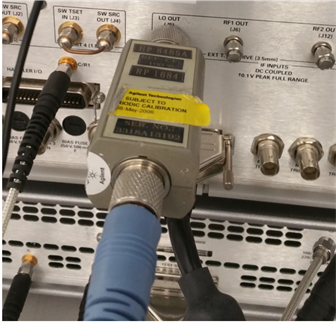
Before starting the LO calibration, disconnect the (Test Set to PNA) rear panel LO cable from the PNA. The Banded LO Cal requires a 3.5 mm Power Sensor to be connected to the PNA rear panel LO connector.
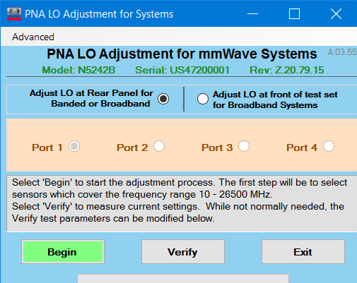
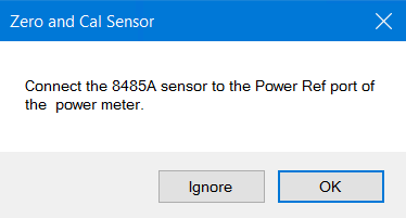
- Click Begin. The following dialog box will appear. Configure a sensor which covers the frequency range 10 MHz to 26.5 GHz. Click OK.
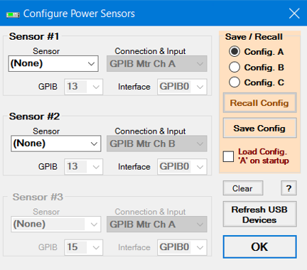
- Zero and Calibrate the Power Sensor.
- Connect the Power Sensor to the PNA Rear Panel LO as shown below.
-
Click Continue to run the LO Calibration. It will be completed in less than a minute. When done, disconnect the Power Sensor from the PNA rear panel and reconnect the Test Set LO Cable.
-
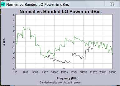
Optionally, you can run the LO CAL Verify by clicking on the Verify button. The first (bottom) trace shows LO Power without the Cal applied. The second (top) trace shows LO power after the Cal is applied. Overlap is normal for frequencies less than 8 GHz and greater than 22 GHz.
RF Calibration
-
In the Banded Installation CAL window, click MM Head RF In Cal. The following dialog box will appear.
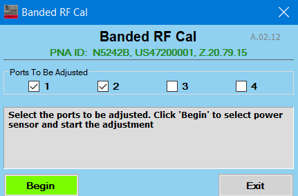
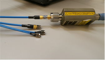
- Configure a sensor which covers the frequency range 10 MHz to 26.5 GHz. Complete the calibration by connecting the power sensor to the end of the N5290A304 adapter cable RF cable as shown below.
-
Click Exit when done with the RF Cal.
IF Calibration
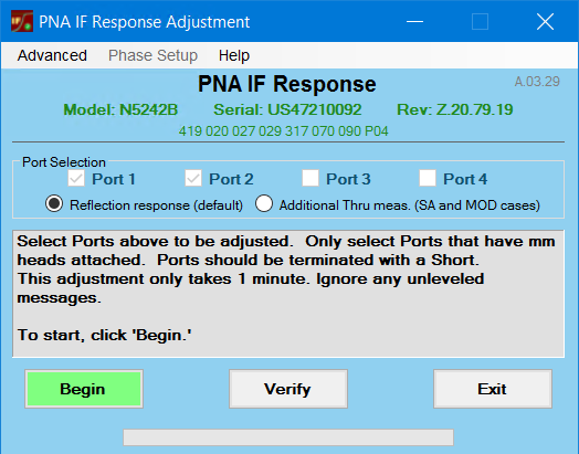
- Turn off the N5292A controller and connect all of the banded modules.
- Turn on the controller and leave all ports open.
- Connect all the LO and RF cables to the modules.
- Click Begin. Once complete the system will be optimized for the best settings to be used by the banded system configured.
MM Source Linearity Cal
The MM Source Linearity Cal is a 2D source calibration (frequency and power). It uses a new dynamic source calibration algorithm that determines the frequencies and powers to sample on the fly. By comparing measured powers in the reference receiver to the provided saturated output powers of the head, a mixer calibration is also performed.
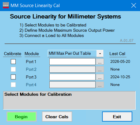
Calibrate: These checkboxes determine which ports will be calibrated.
MM Max Pwr Out Table: Load a PMax table for each port that is selected for calibration. PMax tables contain saturated output powers at different frequencies. (Note: format for file shown below.)
Last Cal: Shows the timestamp of the last calibration acquired for each port.
Begin: Disabled until at least one port is selected and a MM Max Pwr Out Table is provided for each selected port.
MM Max Pwr Out Table file format: The file is a standard PRN file as exported from the PNA, but it includes one extra line at the beginning specifying the mm head input power used to generate the table. Here is a sample:
"InputPower:10dBm"
"PowerSensor,1 Log Mag"
"Freq (Hz)","dBm",
110000000000, 4.719963e+00,
110300000000, 4.734131e+00,
110600000000, 5.153255e+00,
110900000000, 5.307924e+00,
111200000000, 5.506047e+00,
111500000000, 5.586389e+00,
111800000000, 5.767347e+00,
112100000000, 5.911865e+00,
112400000000, 6.110046e+00,
112700000000, 6.194704e+00,
113000000000, 6.357737e+00,
113300000000, 6.423913e+00,
113600000000, 6.425033e+00,
113900000000, 6.452572e+00,
In place of a power table, the calibration can also be performed using a fixed power level. This uses the same saturated output power for all frequencies.
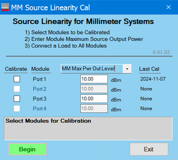
MM Max Pwr Out Level: The saturated output power of the head.