Banded refers to any configuration that is not a broadband configuration and is waveguide based. Frequency extenders cover frequency ranges from 50 GHz to 1.1 THz. The supported solutions can be configured for different frequency bands with the N5292A Test Set controller depending on the measurements required and the frequency extenders being used.
After minimal setup shown below, the N5290A/91A functions the same as a standard VNA. All ports can be used at mmWave frequencies or a combination as required.
The following table shows the waveguide designation equivalents.
| MIL-DTL-85/3C | IEEE Std 1785.1 | Frequency Range |
| WR-15 |
WM-3759 |
50 GHz to 75 GHz |
| WR-12 |
WM-3099 |
60 GHz to 90 GHz |
| WR-10 |
WM-2540 |
75 GHz to 110 GHz |
| WR-08 |
WM-2032 |
90 GHz to 140 GHz |
| WR-06 |
WM-1651 |
110 GHz to 170 GHz |
| WR-05 |
WM-1295 |
140 GHz to 220 GHz |
| WR-04 |
WM-1092 |
170 GHz to 260 GHz |
| WR-03 |
WM-864 |
220 GHz to 330 GHz |
| WR-02 |
WM-570 |
330 GHz to 500 GHz |
| WR-1.5 |
WM-380 |
500 GHz to 750 GHz |
| WR-1.0 |
WM-250 |
750 GHz to 1.1 THz |
| Reference: IEEE Standard for Rectangular Metallic Waveguides and their interfaces for frequencies of 110 GHz and above - Part 1: Frequency Bands and Waveguide Dimensions. | ||
N5292A Test Set
DC Source to provide bias voltage to frequency extenders
Option S93080A/B and 020
Special adapter cable to connect between frequency extender and N5292A Test Set
Source power calibration is required for ALL power related measurements with banded millimeter modules
Banded measurements must use the N5292A Test Set
No DC power connector in N5292A Test Set to provide bias voltage to frequency extenders for banded measurements
No automatic power leveling. However, after performing an Installation Calibration, the source power at the output of the N5293A or N5295A Frequency Extender is adjustable.
Simultaneous broadband and banded measurements NOT supported
Work with your frequency extender vendor to determine appropriate IF Gain settings as necessary. For instance, most VDI supplied extenders require 8 dB IF Gain.
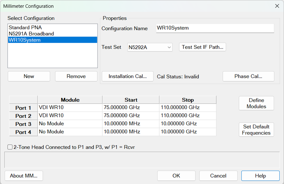
Click on the Define Modules button to open the Module Setup dialog where banded modules can be defined. Set appropriate multiplier values that are specified in your mmWave module documentation. Set the MM output frequency range. Ensure that the RF and LO Frequencies are within the frequency range of the sources. The VNA offers no warning if they are NOT. See Millimeter Configuration.
Assign the modules to each port that has the frequency extender in the Millimeter Configuration dialog module grid.