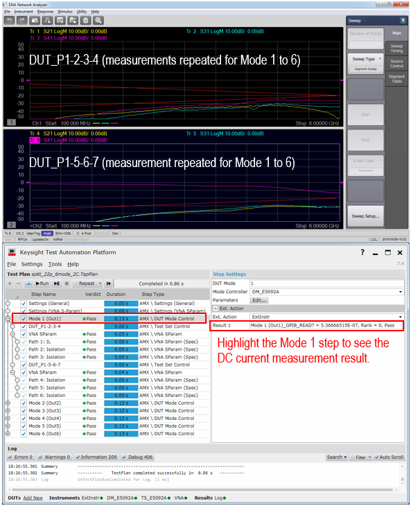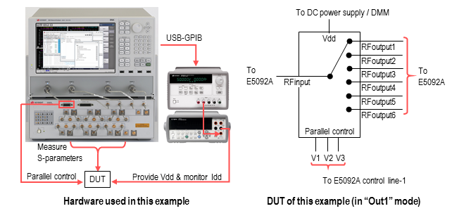
This example shows a procedure for testing a SP6T RF switch with the E5080A based AMX system. The DUT mode (switch state) is controlled with the parallel control voltages from the E5092A’s control line-1 port. To edit the multimode DUT test plan efficiently, Microsoft Excel is used in combination with the AMX Test Plan Builder.

|
Instruments: |
E5080A ENA, E5092A multiport test set (22-port configuration), E3633A DC power supply, 34410A digital multimeter (DMM) |
|||||||||||||||||||||
|
Test parameters |
Insertion loss & isolation between RF input and RF output ports in 6 DUT modes. |
|||||||||||||||||||||
|
Calibration: |
Two sets of full 4-port cal to cover 7 test ports. |
|||||||||||||||||||||
|
Test specs: |
|
|||||||||||||||||||||
|
DUT mode control: |
3-bit parallel control voltages, logic level 3.3 V (same as Vdd level)
Vdd and parallel control voltages are turned on and off before starting and after completing the DUT test sequence. |
The AMX version must be ver.1.5 or above.
The AMX E5092A plugin must be installed to the E5080A in addition to the AMX VNA plugin. Contact your local Keysight office for the plugin.
The VNA firmware version must be A.12.55.05 or above.
|
E5092A |
DUT |
|
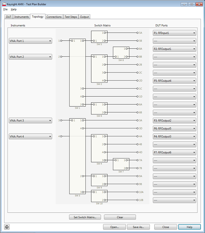
Port 5A |
RF Input 1 |
|
Port 8A |
RF Output 1 |
|
Port 3A |
RF Output 2 |
|
Port 4A |
RF Output 3 |
|
Port 2D |
RF Output 4 |
|
Port 3D |
RF Output 5 |
|
Port 4D |
RF Output 6 |
This example uses the E5092A Control line 1 (D-SUB 15 Pin Connector)
|
Pin No. |
Description |
Parallel control |
|
1 |
Line 1 |
V1 |
|
2 |
Line 2 |
V2 |
|
3 |
Line 3 |
V3 |
|
4 |
Line 4 |
N/A |
|
5 |
Line 5 |
N/A |
|
6 |
Line 6 |
N/A |
|
7 |
Line 7 |
N/A |
|
8 |
Line 8 |
N/A |
|
9 |
N/A |
|
|
10 |
N/A |
|
|
11 |
N/A |
|
|
12 |
DC Source |
This E5092A’s internal DC source is not used in this example. |
|
13 |
Positive input |
5 V from the external DC power supply is connected. |
|
14 |
Negative input |
Connected to GND |
|
15 |
GND |
|
Using Excel template function allows you to create your test plan more easily and quickly when your configuration has many test steps and many parameters for modes and connections. In this example, the setups for Test Step and Mode in test plan is configured on the Excel application using an Excel template.
Launch the AMX Test Plan Builder and File > New
Enter the basic information on the DUT and Instruments, which are required for generating the Excel template in the next step.
|
DUT Tab
|
|
VNA Tab
|
Open the generated Excel template file by the Excel application.
In the “Spec Sheet” tab, click "B2" cell under "mode_label", then select "Mode1 (Out1) from pull-down menu.
Setup the second row ("B") according to the DUT test conditions, by selecting the items from the pulldown menu or typing the value.
Right-click on any cells in the second row ("B") and select “Insert” > "Table Row Below" from the Excel popup menu. The same pull down menus are available in the inserted row.
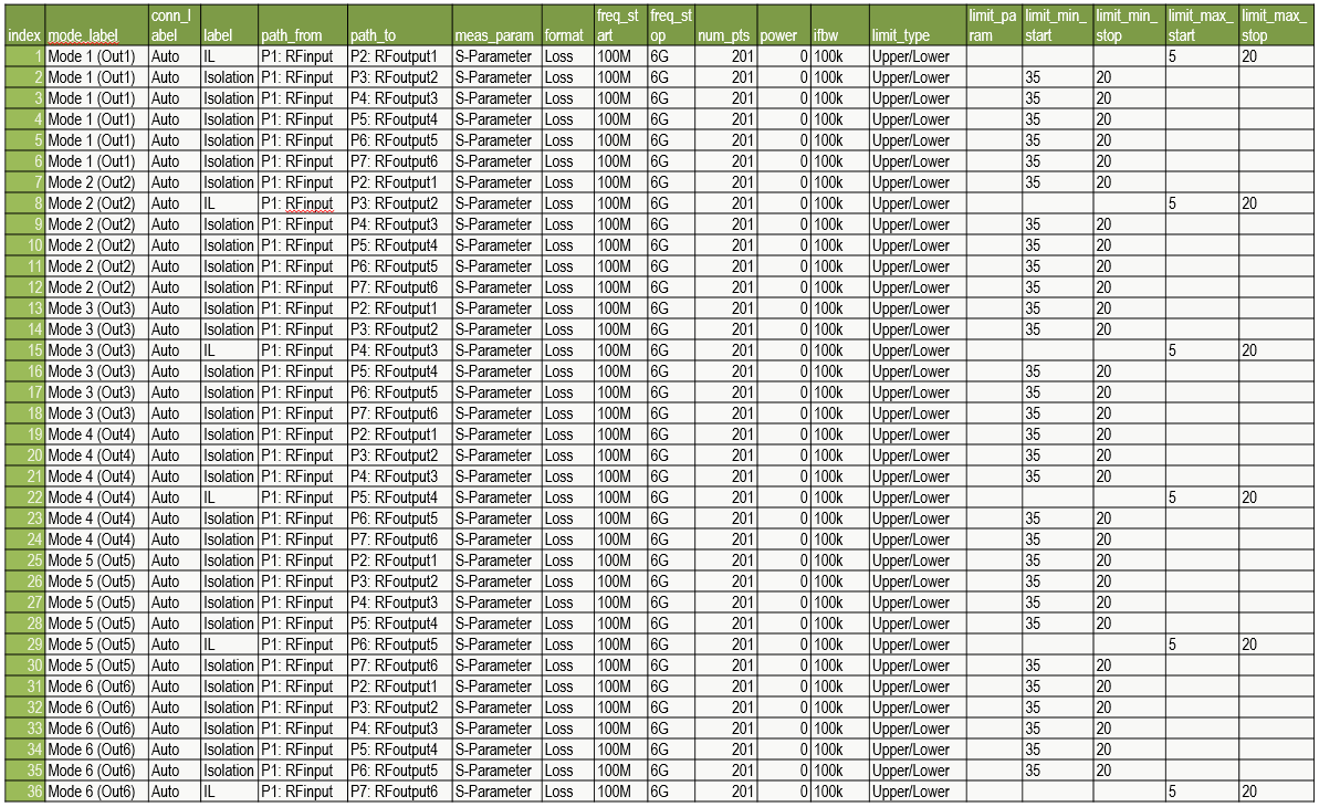
Complete the DUT test conditions and specs as shown below
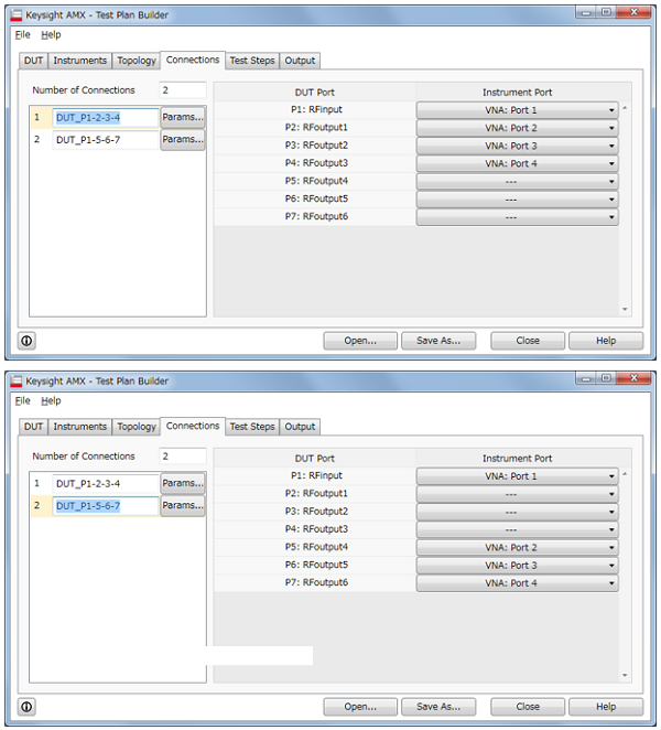
“Connection_label: Auto” automatically selects an appropriate connection pattern from the ones you have registered in the Test Plan Builder before generating the Excel template. In this example, two connection patterns “DUT_P1-2-3-4” and “DUT_P1-5-6-7” using the calibrated 4 test ports were defined and the one suitable for each test item will be automatically selected.
When creating the DUT test plan in the Excel template, the prefixes “Mode x:” and “Px:” (x=1, 2, 3…) are added to the labels you defined in the Test Plan Builder.
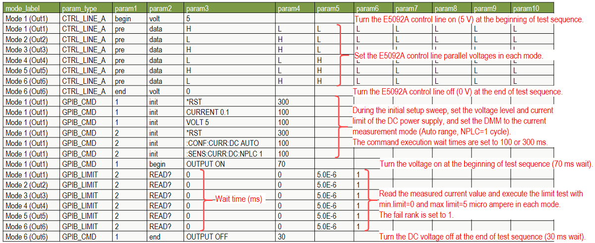
In the “Mode” tab, enter the control sequence of the parallel control voltages of the E5092A and GPIB commands of the DC power supply and DMM. See the for the control parameters. See Controlling E5092A Configurable Multiport Test Set for the control parameters.
When you complete editing the DUT test plan including the control sequence of the E5092A and GPIB, save it as an Excel .xlsx file with your desired filename.
Export the XML file by adding “.ss” to the filename, for example, “DUTtestplan.ss.xml”.
Go back to the Test Steps tab of the AMX Test Plan Builder where you generated the Excel template.
Click [Import Spec Sheet…] and import the ss.xml file you generated. The DUT test plan and the DUT mode control sequence created in the Excel file will be imported to the AMX Test Plan Builder.
Confirm that the information in the Excel file is correctly imported by opening each mode in the Test Steps and DUT tabs.
In the menu bar, select “File” -> “Save As…” and save the test plan file (.tpbproj).
In the Output tab, click [Output Test Plan…] to build and output the TAP test sequence file (.TapPlan) to be executed on the TAP.
Make sure that the E5092A DC power supply, and digital multimeters are turned on and being connected to the E5080A.
Confirm if the back end application (TAP) setup for E5092A is done. See Controlling E5092A Configurable Multiport Test Set.
Confirm if the back end application (TAP) setup for DMM and DC power supply are done. See External Instruments Controller).
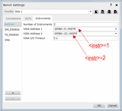
Set Number of Instruments (“2” in this example) and VISA addresses of the DC power supply and DMM (GPIB0::5::INSTR and GPIB0::22::INSTR in this example).
Copy the generated TapPlan file to the E5080A.
Launch the TAP on the E5080A.
Load the .TapPlan file.
Run the TapPlan to execute the initial setup sweep for setting up the VNA.
Confirm that the 4-port ECal module is connected to the PXIe controller.
In the menu bar, select “Settings” -> “AMX/AMX” to launch the Cal Wizard. Execute the calibration by following the guidance.
Connect the TAP resource by clicking ![]() .
.
Run the TapPlan. The DUT test sequence is executed and test results are displayed as shown below. As the test is executed by turning Reuse Channel on, the measurements of all DUT modes are performed by repeating the sweeps in the VNA channel-1 (for the connection “DUT_P1-2-3-4”) and channel-2 (for the connection “DUT_P1-5-6-7”).
Highlight the step of Mode 1 to see the DC current measurement result.
