ADC Clipping
ADC clipping occurs when the signal to the ADC (analog-to-digital converter) exceeds the input voltage range of the ADC.
On oscilloscopes that do not use DSP (digital signal processing) correction, there is a direct correlation between the range of the display and the range of the ADC. The top of the display is the maximum of the ADC range, and the bottom of the display is the minimum of the ADC range.
On oscilloscopes that do use DSP correction (such as the Infiniium oscilloscopes), the same general correlation exists, but to a less accurate degree. The correction that the DSP filters are applying changes the shape of the displayed waveform to be a more accurate representation of the signal being measured. Because the corrected waveshape can be different than the raw uncorrected waveshape, the displayed distance to the top or bottom of the display can also be different, which introduces some uncertainty about when the raw uncorrected signal might be at the limits of the ADC range.
ADC clipping detection is always active regardless of the Run/Stop/Single state. In other words, ADC clipping is independent of the acquisition and is detected even if it occurs before or after the data being acquired. This is known a "off-screen" clipping. ADC clipping is continuously active so that it can alert you to any clipping condition before or after running tests, so that adjustments can be made to the DUT or oscilloscope if necessary.
How Do I Know if ADC Clipping is Occurring?
When ADC clipping is detected, you see an indicator in the waveform content window.
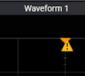
You can select the indicator to see the status details.
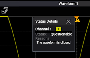
A "Clipped" indicator is also shown on the channel badge.
![]()
ADC clipping is detected on analog input channels only. If analog inputs with clipping are used in math functions, the clipping indicator also appears in the content window that displays the math function waveform.
If analog inputs are paired as differential or common mode waveforms, indicators also appear when clipping is detected on the analog input channels used to create those waveforms.
Note that scaling differential or common mode waveforms will not affect ADC clipping. Instead, undo the channel pairing, adjust the vertical scales on the analog input channels, and then return to pairing channels as differential or common mode waveforms.
How Can I Prevent ADC Clipping from Occurring?
Understanding what conditions cause ADC clipping can help you prevent it. Conditions that can cause unintentional ADC clipping include:
- Displaying the differential or common mode component of multiple channels without displaying the original channels.
- Viewing a math function without also viewing the associated input channels.
- Using an application, such as VSA, that does not always show the original channels.
How Can I Stop ADC Clipping Once it has Occurred?
To stop the clipping once it has occurred, reduce the amplitude of the signal on the channel or change the vertical scale or offset of the channel to make it smaller (use less of the ADC range).