Explicit 1st Order PLL
The Explicit 1st Order PLL recovery method lets you provide a clock from the circuit that you are measuring and apply a first-order PLL.
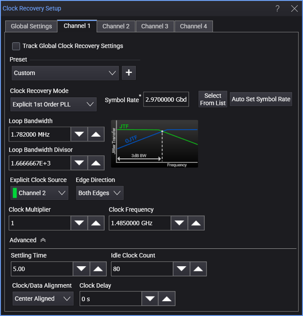
When the Explicit 1st Order PLL clock recovery mode is selected, the dialog box has these controls:
-
Symbol Rate — Displays the signal's measured symbol rate.
For explicit clock recovery methods, Clock Frequency is used in place of Symbol Rate.
The Select From List drop-down menu lets you select typical rates for standard communication interface technologies. The Auto Set Symbol Rate button runs a data rate measurement and populates the Symbol Rate field with the data rate measured on the input signal.
-
Loop Bandwidth — You can specify the PLL's loop bandwidth either by entering it directly in the Loop Bandwidth field (also known as the -3 dB BW) or by entering the Loop Bandwidth Divisor value.
-
Loop Bandwidth Divisor — Enter a number that you divide the Symbol Rate by to get the loop bandwidth.
Explicit Clock Settings
-
Explicit Clock Source — This specifies the input source of the provided clock to be used for clock recovery.
-
Edge Direction — Lets you specify the edges used in the explicit clock: Rising edges, Falling edges, or Both rising and falling edges.
-
Clock Multiplier — This specifies the multiplier of the provided clock to be used.
-
Clock Frequency — The clock frequency of the PLL.