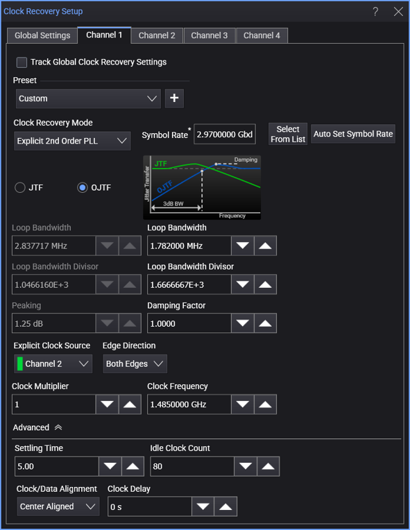
Explicit 2nd Order PLL
The Explicit 2nd Order PLL recovery method lets you provide a clock from the circuit that you are measuring and apply a second-order PLL.
You can specify the PLL's response in terms of either the JTF's 3 dB bandwidth and its peaking or the OJTF's 3 dB bandwidth and its damping factor.
![]()
When the Explicit 2nd Order PLL clock recovery mode is selected, the dialog box has these controls:
-
Symbol Rate — Displays the signal's measured symbol rate.
For explicit clock recovery methods, Clock Frequency is used in place of Symbol Rate.
The Select From List drop-down menu lets you select typical rates for standard communication interface technologies. The Auto Set Symbol Rate button runs a data rate measurement and populates the Symbol Rate field with the data rate measured on the input signal.
-
JTF (Jitter Transfer Function) — This is the closed-loop transfer function of the PLL. It is the ratio of the jitter on the PLL's output clock to the jitter on the input signal.
This function generally has a low-pass effect. That is, JTF is at unity over low frequencies, but as the jitter increases to higher frequencies, the jitter on the recovered clock will decrease in magnitude.
Peaking — When specifying the PLL's loop bandwidth in terms of the JTF 3 dB BW, you also need to specify the peaking of the JTF. See JTF Equations for Second Order PLLs for help in converting from Damping Factor or OJTF peaking to JTF Peaking.
-
OJTF (Observed Jitter Transfer Function, sometimes referred to as the Error Function) — This is the jitter between the PLL's input signal and PLL's output clock. It is equivalent to the PLL's Error Function (OJTF = EF = 1 – JTF).
This function generally has a high-pass effect. That is, OJTF is at unity over high frequencies, but as the jitter decreases to lower frequencies, the jitter on the displayed waveform will decrease in magnitude.
Damping Factor — When specifying the PLL's loop bandwidth in terms of the OJTF 3 dB BW, you also need to specify the damping factor of the JTF.
< 1 underdamped > 1 overdamped = 1.0 critically damped = 0.707 Often considered ideal or optimal because of its fast settling time (optimally flat) and Butterworth type response. See OJTF Equations for Second Order PLLs for help in converting from JTF Peaking or OJTF peaking to Damping Factor.
-
For JTF or OJTF, you can specify the PLL's loop bandwidth either by entering it directly in the Loop Bandwidth field (also known as the -3 dB BW) or by entering the Loop Bandwidth Divisor value (a number that you divide the nominal data rate by to get the loop bandwidth).
As you adjust JTF Loop Bandwidth (or Loop Bandwidth Divisor) and Peaking values, the equivalent OJTF values are also displayed, and vice-versa. In a Second Order PLL, OJTF is not the mathematical complement of JTF, so the equivalent values are different.
Explicit Clock Settings
-
Explicit Clock Source — This specifies the input source of the provided clock to be used for clock recovery.
-
Edge Direction — Lets you specify the edges used in the explicit clock: Rising edges, Falling edges, or Both rising and falling edges.
-
Clock Multiplier — This specifies the multiplier of the provided clock to be used.
-
Clock Frequency — The clock frequency of the PLL.