Jitter Measurements Tab
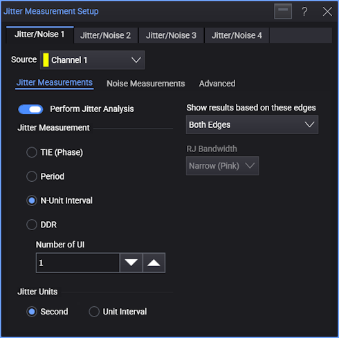
The Jitter Measurements tab in the Jitter Measurement Setup dialog box has these controls:
-
Perform Jitter Analysis — Enables or disables the Jitter analysis.
-
Jitter Measurement — The Jitter analysis can extrapolate TJ from TIE measurements or N-UI measurements:
-
TIE (Phase) — The time difference between each transition and some ideal time reference. Jitter data is accumulated according to a recovered clock.
-
Period — The same as N-UI jitter with an N of 2.
-
N-Unit Interval — Like a recovered clock, N-UI is the time difference between each transition and the transition N unit intervals away from it.
Use the Number of UI field to enter the value of N.
-
DDR — When an explicit clock recovery method is selected (see Clock Recovery), you can select DDR for the jitter measurement.
The DDR mode supports the differences in jitter extrapolation and measurement calculations (particularly Eye Width) that are required when DQS is used as an explicit clock and measurements are made at a UI that is some distance away from the clock edge.
The advanced clock recovery Clock/Data Alignment and Clock Delay settings (see Advanced Clock Recovery Setup) are used to identify the eye on which jitter analysis is performed.
First, note that with Centered Aligned clocks, jitter is measured on the left and right side of the eye in the middle of the eye diagram, and with Edge Aligned clocks, jitter is measured on the eye to the right of the center.
Then, to identify an eye that is a number of UI away from the clock edge, set the Clock Delay to a multiple of the clock period.
This way of identifying the eye on which jitter analysis is performed also aligns the eye and TIE measurement results to the jitter measurement results.
N-Unit Interval and Period jitter can be performed on clock or 1/0 data waveforms only. Because N-UI and period jitter are measured from edge to edge, no clock recovery is required. However, clock recovery is used to validate the pattern length of 2 and to report the data rate.
-
-
Jitter Units — Sets the units of measure for the jitter measurements to either Second (s) or Unit Interval (UI).
-
Show Results Based on these Edges — Selects whether RJ/DJ measurements are made on the Rising Edge, the Falling Edge, or Both Edges (rising and falling).
Jitter measurements performed on clock-type signals typically use a single edge setting, unless both edges of the clock are used to latch data.
In double data rate applications, this control should be set to Both Edges.
-
RJ Bandwidth — The Jitter analysis software uses a spectral technique to separate RJ from PJ.
Narrow bandwidth spikes that extend above the jitter spectrum's baseline are considered to contain PJ, while the remaining baseline is assumed to contain only RJ. This technique works very well for wide-bandwidth (white) random jitter.
Wide bandwidth RJ has a uniform power spectral density (PSD) across the entire jitter spectrum. Sometimes however, the RJ being measured does not have a uniform PSD. Although this is not as common in practical communication system applications, it does occur frequently in jitter sources generated using laboratory test equipment.
Conversely, the jitter spectrum of some PJ components appears much broader than the narrow spikes of a highly periodic jitter component. These broad-bandwidth PJ components are also uncommon, but they can be difficult to distinguish from RJ by inspecting the jitter spectrum alone.
For these reasons, the Jitter analysis software lets you specify whether you want to treat "broad lumps" in the jitter spectrum as RJ or PJ.
-
Wide (White) — Setting the RJ Bandwidth mode to wide (white) assumes that the RJ is flat, and that all broad lumps in the jitter spectrum are considered to be PJ.
-
Narrow (Pink) — Setting the RJ Bandwidth mode to narrow (pink) acknowledges that the RJ may or may not be flat, and that all broad lumps in the jitter spectrum are considered to be RJ.
By default, the RJ bandwidth mode is set to narrow (pink).
The Jitter analysis uses a non-linear decision threshold that can follow the non-flat baseline of RJ. This non-linear threshold is only used in narrow RJ Bandwidth mode because the wide RJ bandwidth mode tells the analysis that you already know that the RJ baseline is flat with frequency.
-