Clock Recovery
Software clock recovery finds an embedded clock or time reference from a source waveform and enables oscilloscope features like real-time eye views, eye measurements, jitter measurements, and other types of analysis.
Clock recovery settings are available in the Clock Recovery Setup dialog box which can be opened by choosing Setup > Clock Recovery... from the main menu.
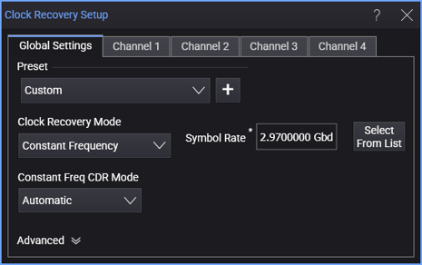
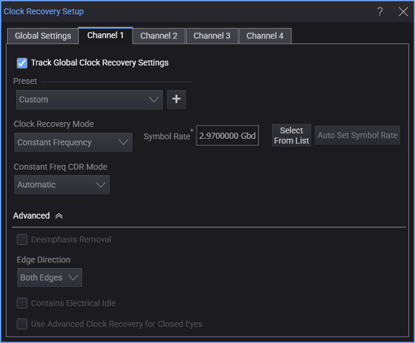
There are tabs across the top for Global Settings and the individual clock recoveries that are enabled. Within the tab for individual clock recoveries, select the Track Global Clock Recovery Settings option to use the global settings.
The Preset controls lets you select from a list of clock recovery settings appropriate for the selected signal type, various technologies, and symbol rates. You can also add your own presets to the list. See Preset.
The Clock Recovery Mode lets you select:
-
Constant Frequency — See Constant Frequency.
-
PLL (Phase Lock Loop) — You can select:
-
1st Order PLL — See 1st Order PLL.
-
2nd Order PLL — See 2nd Order PLL.
-
3rd Order PLL — See 3rd Order PLL.
-
5th Order PLL — See 5th Order PLL.
The PLL clock recovery takes this long to settle:
Settling time(s) = PLL Settling Time / Loop Bandwidth
By default, the PLL Settling Time is 5 time constants. This can be changed in the Advanced settings. The Loop Bandwidth can also be adjusted (see 1st Order PLL and 2nd Order PLL).
If you are making measurements like jitter, the PLL Settling Time should be long enough that the PLL has time to lock to the acquired waveform. If you are making protocol decode measurements and just need a 1 or 0 out, you can often set the PLL Settling Time shorter.
The settling time is independent of the data pattern.
-
-
Explicit Clock Recovery Methods — Use these methods when there is an explicit signal to be used as the clock in serial data and jitter analysis:
-
Explicit Clock — See Explicit Clock.
-
Explicit 1st Order PLL — See Explicit 1st Order PLL.
-
Explicit 2nd Order PLL — See Explicit 2nd Order PLL.
-
Explicit 3rd Order PLL — See Explicit 3rd Order PLL.
The explicit clock recovery methods let you make jitter measurements with respect to the provided clock.
-
-
DDR5 — Use this clock recovery method for DDR5 real-time eye analysis. This method performs clock recovery with read or write discrimination, letting you create a real-time eye of the DQ (Data) waveform. Read or write bursts are separated by analyzing the DQ (Data), DQS (Strobe), and CA4 (Command/Address 4) signals. DDR5 real-time eye can be performed on signals that have had equalization (DFE) applied or on signals without equalization. See DDR5.
-
MIPI M-PHY PWM — Use this clock recovery method for MIPI M-PHY Low Speed Mode. See MIPI M-PHY PWM.