Markers
You can add markers to the oscilloscope's display. Markers let you measure horizontal and vertical values on a waveform.
The quickest way to add a marker is to right-click on a graticule area and choose Place Marker here:
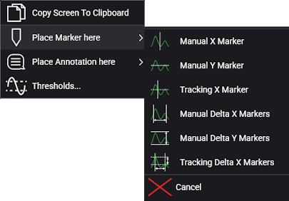
Up to 16 markers are available, and you can select from these types:
- Manual X Marker
- Manual Y Marker
- Tracking X Marker
- Manual Delta X Markers
- Manual Delta Y Markers
- Tracking Delta X Markers
Tracking markers let you specify the X location, and the waveform's Y value at that location is displayed.
Delta markers are pairs that display the difference between two locations.
Markers can be positioned within a grid by dragging. More precise positioning can be set using dialog box fields.
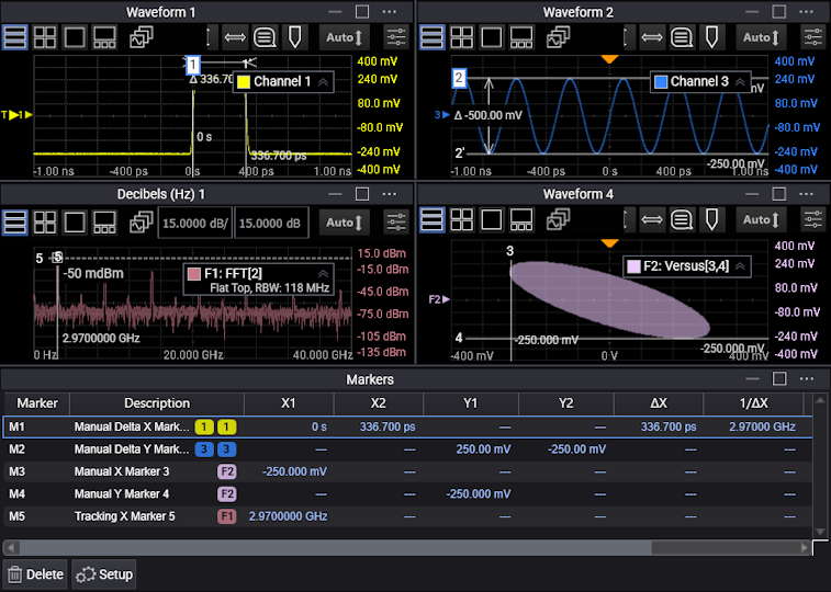
Measured values and marker names are displayed.
Markers can be temporarily hidden and then shown again.
To set up markers:
-
Open the Markers dialog box (Measure > Markers...).
-
In the Markers dialog box, select the tab for the marker you want to set up.
-
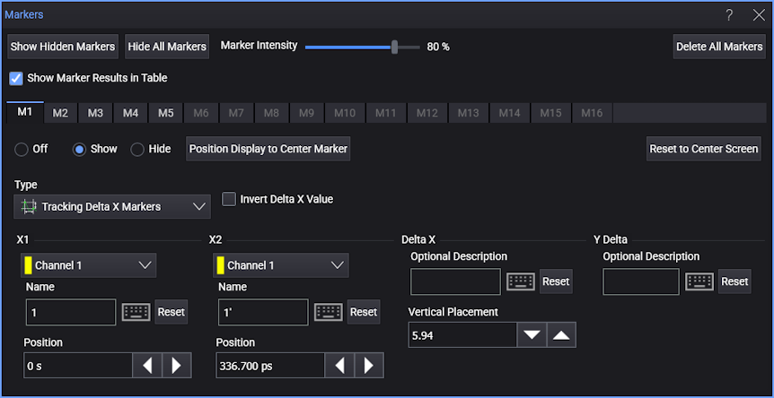
At the top of the Markers dialog box are controls that affect all markers:
-
Show Hidden Markers — Displays any hidden markers.
-
Hide All Markers — Hides all markers without changing any of the marker settings.
-
Marker Intensity — Adjusts the brightness of all marker information on the display.
-
Delete All Markers — Turns all markers off and "defaults" their settings.
-
Show Marker Results in Table — Enables or disables displaying marker results in the Markers content window.
-
-
Within a marker tab, use these controls to set up an individual marker (depending on the selected marker type):
-
Off, Show, Hide — Display, hide, or turn off a marker. No values are changed when a marker is hidden, but turning off a marker can cause some values to be reset.
-
Position Display to Center Marker — Changes the grid's horizontal position in order to center the marker. This can change the horizontal position in other grids as well.
-
Reset to Center Screen — Moves the marker to the center of the grid.
-
Source — Associates the marker with a source waveform and its window and grid. The Delta Marker types let you specify a source waveform for each marker in the pair. You can specify the same source waveform for both markers in the pair.
-
Type — Selects from these types of markers:
- Manual X Marker
- Manual Y Marker
- Tracking X Marker
- Manual Delta X Markers
- Manual Delta Y Markers
- Tracking Delta X Markers
-
Scope — For non-Delta marker types, this option specifies where the marker is displayed:
-
Signal Only — The marker is displayed only in the grid containing the source waveform.
-
Window Only — The marker is displayed in all the grids of the source waveform's content window.
-
Global — The marker is global and is displayed across all waveform content windows with compatible axes. Compatible axes, for example, are Y axes displaying voltage, X axes displaying time, X axes displaying frequency, etc.
-
-
Invert Delta X Value — When selected, "1/value" is displayed instead of "value". Inverted horizontal values, for example, can show the frequency associated with a period of time.
-
Name — Lets you change the marker name.
-
 — Opens the On Screen Keyboard dialog box for entering text or math symbols.
 -
Reset — Returns to the "default" value.
-
Position — Lets you position markers more precisely by entering values in the field or using the decrease and increase buttons.
-
Optional Description — For delta marker types, this field lets you add a description for the measured value.
-
Horizontal Placement, Vertical Placement — For delta marker types, these fields let you adjust the location of the displayed marker value as a percentage of the grid's horizontal width or vertical height.
-