PAM Jitter Measurement Setup
You can open the PAM Jitter Measurement Setup dialog box by choosing Measure > PAM Jitter... from the main menu or by clicking the Setup button in a PAM Jitter content window.
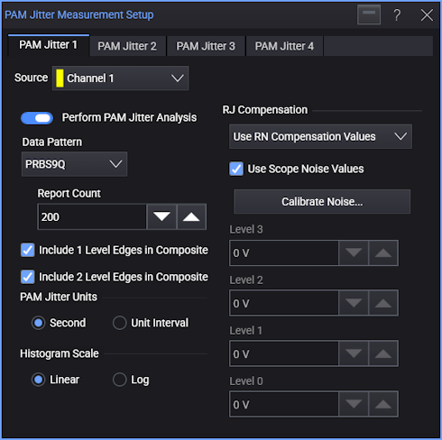
Up to four PAM Jitter analyses can be performed, and there is a tab in the dialog box for each. In each of PAM Jitter Measurement Setup dialog box tabs are these controls:
-
Perform PAM Jitter Analysis — Enable or disables the jitter analysis.
-
Data Pattern — Selects the pattern present in the input signal:
-
PRBS13Q — A repeating 8191-symbol sequence formed by Gray coding pairs of bits from two repetitions of the PRBS13 pattern into PAM-4 symbols.
-
PRBS9Q — A repeating 511-symbol sequence formed by Gray coding pairs of bits from two repetitions of the PRBS9 pattern into PAM-4 symbols.
-
PCIe6 JnU — A 52-symbol pattern for making edge jitter measurements on PCIe Gen6 signals.
-
PCIe6 Dual-Dirac — On a specified 52-UI jitter pattern where each of the 12 edges in PAM-4 are repeated four times, jitter is measured on each of the 48 edges individually and then averaged.
Random Jitter RMS (TTX-RJ) is measured, and the dual-Dirac model is used to return Uncorrelated Total Jitter peak-peak (TTX-UTJ) and Uncorrelated Deterministic Jitter Delta-Delta (TTX-UDJDD) extrapolated to a BER of 1E-6. These measured values appear in the Results pane.
Note that when this option is selected, the Include 1/2 Level Edges In Composite controls are not used because all edges are used in the 48-edge jitter measurements.
-
File — Lets you specify the edges for data pattern by loading its definition from a file.
The format of this file is proprietary. For help developing custom files, contact Keysight Technical Support and ask for an Application Engineer.
-
-
Report Count — The IEEE 802.3bs standard (and other standards) can specify these measurements must be made 10,000 times. However, you can use this field to change the count that is actually used.
-
Include 1 Level Edges In Composite — Specifies whether edges that change one level are included in the analysis.
-
Include 2 Level Edges In Composite — Specifies whether edges that change two levels are included in the analysis.
-
PAM Jitter Units — Specify whether the measurement units should be in Second or Unit Interval.
-
Histogram Scale — Specify whether the PAM-4 jitter histogram graph vertical scales are Linear or Log.
-
RJ Compensation — You can select:
-
Off
-
Use RN Compensation Values — The compensation specified by the Level N fields are used.
If Use Scope Noise Values is selected, click Calibrate Noise... to open the Calibrate Scope Noise dialog box where you can run the automatic oscilloscope random jitter/noise calibration. When the calibration completes, the calibrated values populate the Level N fields.
-
Remove Custom Jitter Value — Use the related field to enter the amount of random jitter to remove.
-