Setting Up Phase Noise Analysis Measurements
To set up phase noise analysis measurements:
-
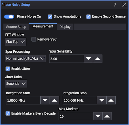
In the Phase Noise Setup dialog box, select the Measurement tab.
-
In the FFT Window drop-down list, select the FFT windowing option.
-
If your clock source uses spread-spectrum clocking (SSC), you can enable Remove SSC to remove the SSC effects from the phase noise analysis results.
-
For Spur Processing, you can select:
-
Normalized (dBc/Hz) — The displayed phase noise trace treats the spurs like noise in dBc/Hz.
-
Omit — The displayed phase noise trace identifies and removes spurs.
-
Power (dBc) — The displayed phase noise trace identifies and rescales spurs in dBc.
Note that the spurs selection can affect phase jitter measurement results. See Measuring Phase Jitter on the Phase Noise Results.
-
-
For the Omit and Power (dBc) spurs selections, where the application identifies spurs from noise, the Spur Sensibility value is used to calculate a threshold for identifying spurs. The threshold is "sensibility × standard deviation (σ)", where standard deviation is calculated from the measurement result moving average.
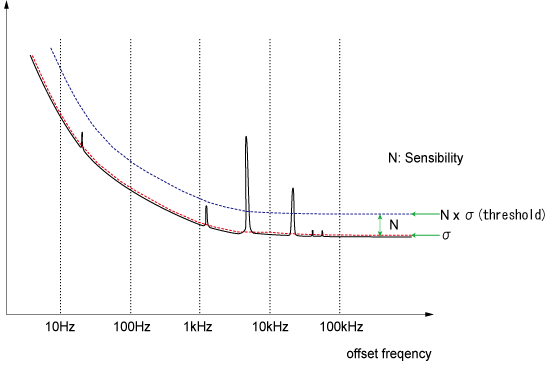
When the measured value exceeds the threshold, it is defined as a spur.
Decreasing the Spur Sensibility value increases the application's ability to sense smaller spurs that are very close to the noise.
Measuring Phase Jitter on the Phase Noise Results
Once the phase noise analysis is set up, you can measure integrated phase jitter from the phase noise log frequency plot.
To add the Phase Jitter measurement:
-
Select Enable Jitter.
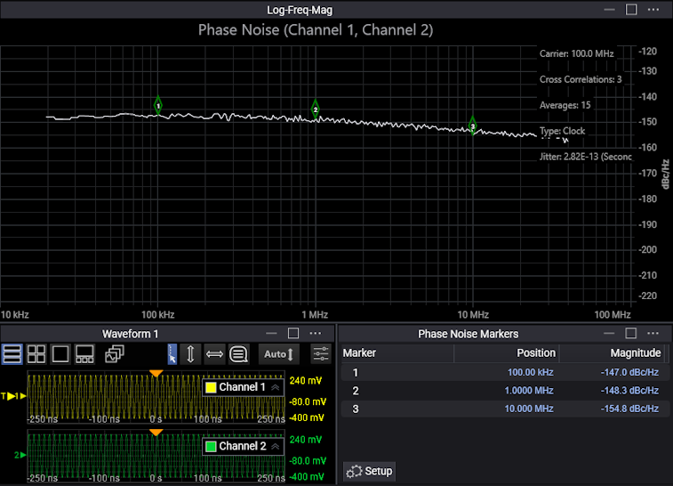
The Phase Jitter measurement over the integration span result is displayed along with other annotations in the Phase Noise waveform content window.
-
Specify the integration span's Integration Start and Integration Stop frequency values.
-
Select the dBc or Seconds (rms) measurement units.
Note that phase jitter measurement results are affected by the phase noise Spur Processing selection in the Measurement tab of the Phase Noise Setup dialog box:
-
Normalized (dBc/Hz) — When measuring phase jitter with this selection, all points in the phase noise trace are integrated across the specified frequency range as if they all represent noise scaled by dBc/Hz.
-
Omit — When measuring phase jitter with this selection, points in the phase noise trace are integrated across the specified frequency range after all points identified as spurs are corrected to remove the portion of the measured value that is due to the spur power. So, the phase jitter due to the spurs is not included in the measurement result.
-
Power (dBc) — With this selection, the phase jitter due to noise and spurs are computed separately and subsequently combined into the final reported measurement value. The noise component is computed as described for the Omit selection. The spur component is computed by combining the phase jitter from all the identified spurs after they are rescaled to dBc.
Markers Every Decade
When Enable Markers Every Decade is selected, markers are automatically placed along the horizontal axis at decade boundary locations. The Max Markers field can limit the number of markers that are placed. The magnitudes of the phase noise plot at the marker locations are displayed in a Phase Noise Markers content window.
The markers can be moved to non-decade boundary locations, and the marker positions and magnitude values are updated in the Phase Noise Markers content window.
To reset markers to the decade boundary positions, you can disable and re-enable the Enable Markers Every Decade control or, in the Display tab, you can adjust the X Start and X Stop frequency scale settings.
See Also
- For more information on the Phase Jitter measurement, see "RJ calculation from phase spectral density" in the application note
 Using Clock Jitter Analysis to Reduce BER in Serial Data Applications.