Setting Up Phase Noise Analysis Sources
To set up phase noise analysis sources:
-
Input the clock source signal(s) to the oscilloscope's input channel(s).
Split the clock source signal into two oscilloscope input channels, or if the clock source is a differential signal, input the positive and negative polarities of the signal into two oscilloscope channels.
The phase noise analysis uses the two-channel cross-correlation technique that can lower the oscilloscope's phase noise measurement floor.
You can use only one clock source input as well, but the analysis is not able to lower the oscilloscope's phase noise measurement floor using two-channel cross-correlation.
-
Display and scale the waveforms that will be included in the phase noise analysis.
Center the waveforms on the display and use most of the vertical range.
-
Add a frequency measurement on the clock source input.
You will use this value in the next step when applying bandpass filters to the input channels.
-
Apply a bandpass filter to the input channels.
In the channels Setup dialog box (select the colored portion of the channel badge), enable Bandpass filters at the measured clock frequency.

Bandpass filtering is commonly used with jitter and phase noise measurements to eliminate aliased out-of-band noise and jitter. You need to use a bandpass filter, for example, to compare oscilloscope phase noise results with a phase noise measurement system like the E5052B signal source analyzer. The built-in bandpass filter applied by Infiniium oscilloscopes sets the bandwidth equal to the center frequency.
For example, for a 100 MHz carrier frequency, a bandpass filter centered around 100 MHz is recommended.
-
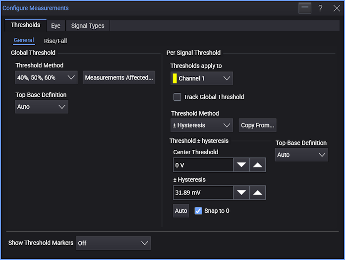
Specify the threshold voltage levels for the input channel(s).
In the Thresholds tab of the Configure Measurements dialog box (choose Measure > Thresholds...), uncheck Track Global Threshold, select the ± Hysteresis threshold method, and click Auto.
-
Specify the Constant Frequency clock recovery option for the input channel(s).
In the Clock Recovery Setup dialog box (choose Setup > Clock Recovery...), uncheck Track Global Clock Recovery Settings, and select Constant Frequency.
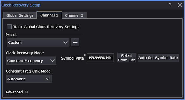
The PLL clock recovery methods will filter out low-offset-frequency phase noise.
-
Specify the acquisition options.
In the Acquisition tab of the Infiniium Scope Setup dialog box (choose Setup > Acquisition...), uncheck Automatic analog sampling rate and analog memory depth.
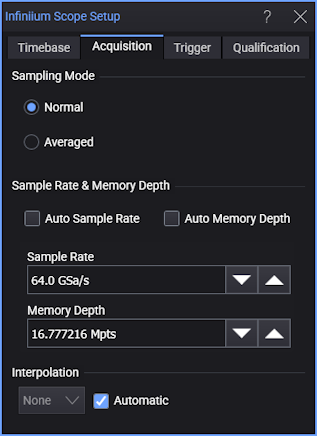
Generally, you want a high sampling rate and you want deep memory to measure offset frequencies that are close to the carrier frequency (although this will increase the time to make calculations).
-
When using two analog input channels, deskew the signals on the input channels. The two sources to the phase noise measurement need only be deskewed to about 5-10% of the signal's period.
In the second channel Advanced Setup dialog box (select the colored portion of the second channel badge, and in the Setup dialog box, click Advanced...), enter the appropriate value in the Skew field.
-
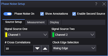
From the main menu, choose Measure > Phase Noise Function... to open the Phase Noise Setup dialog box.
-
Select the clock source input channels using Signal Source One and, when Enable Second Source is selected, Signal Source Two.
Select an analog input channel (or Magnify or Average math function).
The oscilloscope phase noise measurement floor is reduced by using two input channels (see Two-Channel Cross-Correlation Lowers the Oscilloscope Noise Floor). You can split a single-ended signal into two copies or you can use both polarities of a differential signal (see Clock Signal Probing Options).
If you do not want to use two input channels, select Empty. With only one input channel, the analysis is not able to lower the oscilloscope's phase noise measurement floor using two-channel cross-correlation.
-
When using two input channels, specify the number of correlations that will be accumulated between averages.
The phase noise single-sideband (SSB) frequency offset plot will average results when acquisitions are running, which will smooth the roughness of the phase noise trace. Increasing the number of correlations will lower the oscilloscope's measurement noise floor but also slow down averaging.
Select the # Cross Correlations that will be accumulated between averages.
-
Specify the edges to measure.
For Clock Edge Selection, choose the edge(s) used for clocking in your device under test (DUT). Generally, you should use both edges for double-data rate applications and a single edge otherwise.
-
Finally, to begin the phase noise analysis, select the Phase Noise On check box.