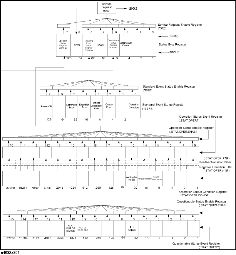
The status reporting system has a hierarchical structure as shown in the figure below. The status byte register is a summary of registers in the lower level. This section describes status registers in each hierarchy.
Status Register Structure
Status Bit Definitions of Status Byte (STB)
|
Bit Position |
Name |
Description |
|
0, 1 |
Not used |
Always 0 |
|
2 |
Error/Event Queue |
Set to "1" if the error/event queue contains data; reset to "0" when all of the data has been retrieved. |
|
3 |
Questionable Status Register Summary |
Set to “1” when one of the enabled bits in the status event status register is set to “1.” |
|
4 |
MAV (Message Available) |
Set to “1” when the output queue contains data; reset to “0” when all of the data has been retrieved. |
|
5 |
Standard Event Status Register Summary |
Set to “1” when one of the enabled bits in the status event status register is set to “1.” |
|
6 |
RQS |
Set to “1” when any of the status byte register bits enabled by the service request enable register is set to “1”; reset to “0” when all of the data has been retrieved through serial polling. |
|
7 |
Operation Status Register Summary |
Set to “1” when one of the enabled bits in the operational status register is set to “1.” |
Status Bit Definitions of Event Status Register (ESR)
|
Bit Position |
Name |
Description |
|
0 |
Operation Complete |
Set to “1” upon completion of all operations done by commands that precede the *OPC command. |
|
1 |
Not used |
Always 0. |
|
2 |
Query error |
1. Set to “1” when the E4982A receives a data output request but there is no data to output. 2. Set to “1” when the data of the E4982A's output queue has been cleared because of a new message received before the completion of data output. |
|
3 |
Device Dependent Error |
Set to “1” when an error has occurred and the error is not a command, query, or execution error. |
|
4 |
Execution Error |
1. Set to “1” when any parameter in a GPIB command exceeds its input range or is inconsistent with the E4982A's capabilities. 2. Set to “1” when a GPIB command cannot be properly executed due to some condition of the E4982A. |
|
5 |
Command Error |
1. Set to “1” when an IEEE 488.2 syntax error occurs (a command sent to the E4982A does not follow the IEEE 488.2 syntax). Possible violations include the command parameter violating the E4982A listening formats or being unacceptable. 2. Set to “1” when a semantic error occurs. Possible causes include a command containing misspellings being sent to the E4982A or an IEEE 488.2 command that is not supported by the E4982A being sent. 3. Set to “1” when GET (Group Execution Trigger) is input while a program message is being received. |
|
6 |
Not used |
Always 0. |
|
7 |
Power ON |
Set to "1" when the E4982A is powered ON. |
Status Bit Definitions of the Operation Status Condition Register
|
Bit Position |
Name |
Description |
|
0 to 2 |
Not used |
Always 0. |
|
3 |
Analog Measurement |
Set to "1" during analog measurment.*1 |
|
4 |
Measurement |
Set to "1" during measurement.*2 |
|
5 |
Waiting for Trigger |
Set to "1" when the instrument is waiting for a trigger.*3 |
|
6 to 15 |
Not used |
Always 0. |
*1. This is when the handler interface’s /INDEX signal is active.
*2. This is when the handler interface’s /EOM signal is active.
*3. This is when the trigger system is in trigger wait state. For more information on the trigger system, refer to Trigger system.
Status Bit Definitions of Questionable Status Event Register
|
Bit Position |
Name |
Description |
|
0 to 4 |
Not used |
Always 0. |
|
5 |
PLL Unlock |
Set to "1" when a PLL unlock occurs. |
|
6 to 8 |
Not used |
Always 0. |
|
9 |
OUT OF GOOD BINS |
Set to "1" when the bin sorting result is OUT OF GOOD BINS.*1 |
|
10 |
RDC OUT OF RANGE |
Set to "1" when the result of Rdc measurement fails to fall within the specified limit range. |
|
11 to 15 |
Not used |
Always 0. |
*1. This is when the handler interface's /OUT_OF_GOOD_BINS is active (the DUT is sorted into the bad bin or not sorted into any bin).
Other topics about Status Reporting System