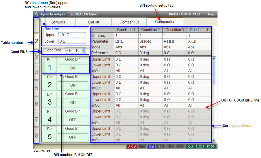
The BIN sorting setup display shown in the following figure appears when you press the Stim Table key the required number of times.
When the Comparator tab is displayed in front of the other three tabs, the screen shows the bin sorting setup display. If another setup display appears, click this tab or press Stim Table key several times to get the bin sorting setup display.
Highlights the active table number. The E4982A has eight tables and each table allows a maximum of 201 measurement points to be set. Use the measurement point setup display to set the measurement point conditions (measurement frequency, averaging factor, oscillator level for the measurement point number) for each table.
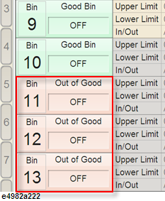
Allows you to set the number of BINs as good bins and bad BINs. For example, Good Bin ~ Bin 10 sets BINs 1 to 10 as good and BINs 11 to 13 as bad bins. The bad bins are highlighted in red, as shown below.
Allows you to set the upper and lower limit values for the DC resistance (Rdc) measurement result.
Allows you to set the bin number and ON/OFF state. You can set the conditions for sorting parts into a maximum of 13 bins. If you turn OFF a bin, the bin is regarded as non-existent.
This area is used to set the sorting conditions for each bin. Four sorting conditions are applied to each bin, and the components that meet all four of a bin’s conditions are sorted into that bin.
This line indicates the last GOOD BINS and can be placed at the desired BIN boundary. To position this line, click on the drop-down button of GOOD BINS to choose the BIN number (indicating the last GOOD BIN). Components sorted into BINs below this line are judged as OUT OF GOOD BINS. The OUT OF GOOD BINS judgment result can be confirmed when the display color of the item ‘BIN sort result’ changes to red. This signal is also output to the handler interface. For more information, refer to OUT OF GOOD BINS Setting.