Other topics about Calibration
Perform the fixture compensation as follows:
If the oscillator level is greater than 500 mV, an error, REDUCE OSC LEVEL or BRIDGE UNBALANCED may occur during the Short correction and measurement may not be correct. When you set the oscillator level for measurement to 500 mV or even greater, set it to 500 mV for the fixture correction.
Fixture compensation consists of three compensation data acquisition processes: OPEN, SHORT, and LOAD, but you do not need to obtain all three types of compensation data when you perform fixture compensation. Each type of compensation data can be turned on or off independently for measurement. For normal measurement, it is recommended that you perform fixture OPEN compensation and fixture SHORT compensation.
For the E4990A, because the sending and receiving ends of a measurement path are terminated with the characteristic impedance of 50 Ω at a measurement frequency of 15 MHz or higher frequency for no cable extension (direct connection type test fixture) or a measurement frequency of 5.2083 MHz or higher for 1 m/2 m cable extension, the trace may contain a gap at 15 MHz (or 5.2083 MHz). You can remove this gap by executing the Load correction.
Press the Cal key to display the Calibration Menu.
Select the calibration (compensation) data acquisition points in accordance with Selecting Calibration/Compensation Data Points.
Press Fixture Compen to display the Fixture Compensation Menu.
If required, set user-defined standard values in accordance with Defining the Standard Values for Fixture Compensation.
When you perform fixture LOAD compensation for the 16334A Tweezers Type Test Fixture or 16451B Dielectric Test Fixture, you need special setups and procedures for standard definition and other processes. See Fixture_Compensation_When_the_16451B/16334A_is_Used for details.
When you complete the changes, press Return to return to the Fixture Compensation Menu.
Put the test fixture's device contacts in the OPEN state.
Refer to the operation manual furnished with each test fixture for more information on the OPEN state of the test fixture. Generally, the OPEN state can be made by connecting no device to the device contacts. If the distance between the HIGH electrode and the LOW electrode can be adjusted for a test fixture, keep the same distance as when the test device is inserted between the electrodes.
Press Open to start OPEN compensation data measurement. When OPEN compensation data measurement is completed, the softkey label changes to Open √.
Put the test fixture's device contacts in the SHORT state.
Refer to the operation manual furnished with each test fixture for more information on the SHORT state of the test fixture. Generally, the SHORT state can be made by connecting a high conductivity metal (shorting bar) to the device contacts or by shorting the HIGH electrode and LOW electrode directly.
Press Short to start SHORT compensation data measurement. When SHORT compensation data measurement is completed, the softkey label changes to Short √.
Connect a LOAD device to the test fixture's device contacts.
Refer to the operation manual furnished with each test fixture for more information on the necessity or connection of LOAD compensation.
Press Load to start LOAD compensation data measurement. When LOAD compensation data measurement is completed, the softkey label changes to Load √.
During the calibration data measurement, the message Sweeping... is displayed in the instrument state area at the bottom-left of the screen.
The fixture compensation function is automatically turned On after completing each compensation data measurement. However, you can turn the function ON or OFF as required.
Press Cal > Fixture Compen to bring up the Fixture Compensation Menu.
Toggle between ON|OFF at OPEN, SHORT and LOAD to make each fixture compensation valid (ON) or invalid (OFF) for the measurement.
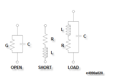
You can define standard values of OPEN, SHORT, and LOAD for fixture compensation. Figure below shows the circuit models of the fixture compensation kit used for the Keysight E4990A.
Each calibration’s standard value can be confirmed and changed as follows:
Press the Cal > Fixture Compen > Define Value to display the Compensation Data Definition Menu.
Select one of the calibration data definition keys, Open Conduct (G), Open Cap (C), Short Resist (R), Short Induct (L), Load Resist (R), Load Induct (L), or Load Cap (C), to confirm or set the compensation data definition.
Enter the desired value to specify the compensation data definition.