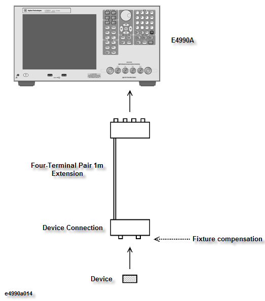
This section describes the calibration procedures to follow when the four-terminal pair port of the E4990A is extended with a 1-meter-long four-terminal pair configuration and the device is connected to the cable’s end with a minimal connection.
This calibration procedure is applied to the following connections:
The 16048G (1-m Cable) is connected to the E4990A and device is connected to the cable’s end with a test fixture.
The 16048G (1-m Cable) is connected to the E4990A and 16452A (Liquid Test Fixture) is connected to the end of the cable.
The 16334A (Tweezer Type Test Fixture) is connected to the E4990A.
The 16451B (Dielectric Test Fixture) is connected to the E4990A.
Make sure that the adapter selection is set to 4TP 1M. Perform Adapter Setup if it is not done yet.
Perform the fixture compensation in accordance with Fixture Compensation.
When you perform only the fixture OPEN compensation and fixture SHORT compensation, follow the normal fixture compensation procedures described in Fixture Compensation.
If you perform the LOAD compensation in addition to the OPEN and SHORT compensations, set the standard values as described below in accordance with the procedures in Defining the Standard Values for Fixture Compensation.
For the 16334A over 3 MHz measurement, the load compensation is recommended according to the following procedure. The proportional error factor in the additional error caused by the fixture is in proportion to the frequency squared. Therefore, the error increases greatly as the frequency goes high.
Set the 100 Ω SMD resistor on the direct connection type fixture (like 16034G), and perform measurement at 3 MHz to determine the value of the 100 Ω SMD resistor.
Set the measured resistance and inductance values to the instrument as load value.
Perform load compensation of the 16334A.
For 16451B, see the table of load value in 2.4.5 Operation Method of http://literature.cdn.keysight.com/litweb/pdf/5980-2862EN.pdf.
Other topics about Calibration