Other topics about Setting Measurement Conditions
The E4990A has one trigger source. When this trigger source detects a trigger signal that has occurred, a sweep or point measurement is performed for channels.
The execution of measurement for each channel does not depend on whether the channel is displayed. Channels that have been activated can be measured even if they are not displayed.
For each channel, a sweep is performed only for the stimulus ports required to update the parameters of the displayed trace.
The trigger source generates a cue signal that initiates a measurement process. Four types of trigger sources are available:
Press Trigger > Trigger Source, then select the desired trigger source.
|
Trigger Sources |
Function |
|
Internal (Internal) |
Uses a consecutive signal generated by the firmware as a trigger source. Triggers are sent immediately following the completion of each measurement. |
|
External (External) |
Uses the external trigger input terminal (BNC) as a trigger source. |
|
Manual (Manual) |
A trigger is generated by pressing Trigger > Trigger. Press Trigger > Restart to regenerate trigger. |
|
Bus (Bus) |
A trigger is generated through GPIB/LAN/USB. |
The point trigger provides a point measurement at every trigger, and it can be used to change the trigger event to point trigger mode.
Press Trigger > Trigger Event, then select the desired trigger event.
|
Softkey Label |
Function |
|
On Point |
Measures at each measurement point. |
|
On Sweep |
Measures all measurement points. |
When the trigger source is the internal trigger, the point trigger does not work
See Setting with Time Delay at Measurement Point for time chart.
When External is selected as a trigger source, click Ext Trig Input to select trigger polarity.
|
Softkey Label |
Function |
|
Negative Edge |
Detect external trigger with negative edge. |
|
Positive Edge |
Detect external trigger with positive edge. |
Set the external trigger delay time at each point. The trigger delay works when the trigger source is set to external.
Press Trigger > Trig Delay.
Enter an external trigger delay time.
See the timing chart for sweep.
External trigger pulses which are supplied until the next measurement becomes ready after the start of a one-point measurement, are ignored, and the next trigger is generated by a pulse supplied after the completion of the one-point measurement.
The time until the next trigger can be accepted after the start of a one-point measurement depends on the IFBW and other settings of the analyzer. For example, in the case of a frequency's zero-span measurement, the time until the next measurement is ready after the start of a one-point measurement is obtained by dividing the time required for a single sweep in On Sweep mode, instead of On Point mode, by the number of measurement points. If you use the point trigger function with external trigger pulses that are wider than this time, point trigger measurement is performed at each pulse input.
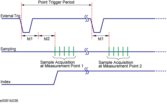
The figure below shows the timing chart of an external trigger when the point trigger function is on.
Timing chart of external trigger (trigger source = external)
The table below describes signals and time as shown in the above figure.
|
Signal, time |
Description |
|
External Trig |
External trigger signal to be supplied. |
|
Sampling |
Time while the E4990A is actually performing measurement. |
|
Index |
Index signal of the handler I/O port. When the point trigger function is ON, it goes to the High level only before starting the measurement of the first sweep point and returns to the Low level after completing the measurement of all the measurement points. |
|
Point Trigger Period |
Time until the E4990A is ready to accept a trigger for the next measurement point. The value depends on the measurement conditions and the settings of the E4990A. |
|
td1 |
Time set as the external trigger delay time. |
|
td2 |
Time for sweep delay. |
You can set the trigger mode for each channel independently. This allows you to control the operation of each channel after a trigger signal is detected by setting the channel's status with the trigger mode.
Press Channel Next (or Channel Prev) to select the channel for which the trigger mode will be set.
Press Trigger, then select the desired trigger mode.
|
Softkey |
Function |
|
Hold |
Sets active channel trigger mode to hold. |
|
Single |
Sets active channel trigger mode to single sweep. |
|
Continuous |
Sets active channel trigger mode to continuous sweep. |
|
Hold All Channels |
Sets all channel trigger modes to hold. |
|
Continuous Disp Channels |
Sets trigger modes of all displayed channels (Display > Allocate Channels) to continuous sweep. |
Repeat the procedure until each channel is set to its trigger mode.
The trigger scope specifies the scope of the triggering, whether it is for all channels or for the active channel.
For example, when Trigger > Continuous is selected for all the channels and the trigger scope is set to active channel, a measurement channel is automatically changed by changing an active channel.
Press Trigger > Trigger Scope, then select the desired trigger scope.
|
Softkey Label |
Function |
|
All Channel |
Sets active channel trigger mode to hold. |
|
Active Channel |
Triggers Active channel alone. |
Press Trigger > Continuous to select continuous sweep.
When continuous sweep is selected, sweeping can be repeated unlimited times after it is triggered. Press the Hold key to stop the sweeping. No further sweeping can be triggered after it is stopped.
Press Trigger > Hold to stop the sweep.
Pressing the Hold key immediately stops sweeping, regardless of which sweeping state (single, specified times, or continuous) is selected. No further sweeping can be triggered after it is stopped.
To perform a segment sweep, you must define two or more frequency ranges, called segments, and then specify the number of points, OSC level, Bias Level, measurement time, sweep delay time, and sweep time for each segment. All segments are swept sequentially as if swept in one sweep operation.
You can define the optimum measurement conditions for each of the segments you designate. For example, you can specify as many points as possible in a segment requiring high trace resolution and as few points as possible in a segment not requiring high resolution. This shortens the measurement time, enabling you to optimize the overall measurement throughput by not having to perform the entire operation under the same measurement conditions of a particular frequency range.
Set the segment sweep with the segment sweep table.
Press Sweep Setup display the sweep setup menu.
Press Edit Segment Table. The segment table appears in the lower section of the screen.
Select the softkey below to change the frequency range setting mode for each segment.
|
Softkey Label |
Function |
|
Freq Mode |
Switches the frequency range setting mode (Start/Stop or Center/Span) |
|
List OSC Level |
Toggles ON/OFF the OSC level setting for each segment; the column for OSC Mode and OSC Level only appears in the segment table when this is turned ON |
|
List Bias |
Toggles ON/OFF the bias setting for each segment; the column for Bias Mode and Bias Level only appears in the segment table when this is turned ON |
|
List Meas Time |
Toggles ON/OFF the measurement time setting for each segment; the column for Meas Time only appears in the segment table when this is turned ON |
|
List Average |
Toggles ON/OFF the averaging value setting for each segment; the column for Point Avg only appears in the segment table when this is turned ON |
|
List Segment Time |
Toggles ON/OFF the segment sweep time setting for each segment; the column for Segment Time setting only appears in the segment table when this is ON |
|
List Segment Delay |
Toggles ON/OFF the sweep delay time setting for each segment; the column for Segment Delay setting only appears in the segment table when this is ON
|
To execute a segment sweep by using the segment table you have created, you must specify the sweep type for that sweep operation by following the steps below.
Press Sweep Setup display the sweep setup menu.
Press Sweep Type > Segment.
Define the method of displaying traces when the segment sweep is executed by following the steps described below.
Press Sweep Setup display the sweep setup menu.
Press Segment Display > Freq Base|Order Base.