Guided Power Calibration


Source and Receiver Power Calibration can be performed during a standard S-parameter Guided Calibration. This power cal provides the following enhancements over the standard source and receiver power calibration:

Note:  A Guided Power Calibration is not accurate when Frequency Offset Mode is enabled.

Learn more about the standard Source and Receiver Power Cals.


In this topic:

How to perform a Guided Power Cal

  1. In a Standard (S-parameter) channel, setup your measurements (sweep type, frequency range, IFBW, and so forth).

  2. Connect the Power Meter / Sensor the same as a standard Source Power Cal. Learn more.

  1. Start the Cal Wizard, then select Guided (Smart) Cal. Learn how.


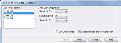
On the following Select Ports dialog, check Calibrate source and receiver power, then click Next.


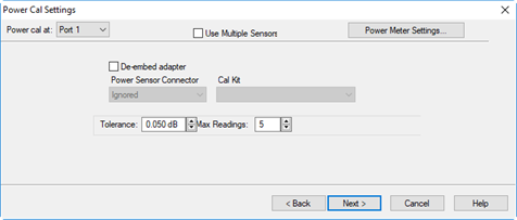
Two Cal Wizard pages later, complete the following dialog.

Power Cal Settings dialog box help

Power Cal at: Select the source port for which a Power Calibration will be performed. The source and receiver correction will be transferred to all other sources and receivers involved in the S-parameter measurements.

Use Multiple Sensors

Check this box to use one or more power sensors that are configured as PMAR devices. This dialog is replaced with the Multiple Sensors dialog. See following image.

When "Use Multiple Sensors" is cleared (default setting), click Power Meter Settings to configure the power meter.

De-embed (power sensor) adapter  When the power sensor connector is NOT the same type and gender as the DUT connector for the specified port, then for optimum accuracy, extra cal steps are required to measure and correct for the adapter that is used to connect the power sensor to the reference plane.

Clear this box to NOT compensate for the added adapter.

Check this box to perform extra calibration steps to measure and correct for the adapter.

Then select the Power Sensor Connector type and gender of the power sensor. "Ignored" does NOT compensate for the added adapter, just as if the checkbox were cleared.

When this connector matches the DUT connector for the same port, then the VNA assumes that there is no adapter. Extra cal steps are NOT required and the Cal Kit selection is not available.

Otherwise, select the Cal Kit to be used to calibrate at the adapter.

See Accuracy Settings below.


Power Cal Settings - Use Multiple Sensors dialog box help

Notes

"Multiple sensors" are allowed ONLY on standard channels, SMC and Cal All calibration.

The power sensors that are used as "multiple sensors" MUST be configured PMAR devices.

Power Cal at: Select the source port for which a Power Calibration will be performed. The source and receiver correction will be transferred to all other sources and receivers involved in the S-parameter measurements.

Sensor Settings  Click to start the Sensor Settings dialog, used to ADD / Configure an External Device.

Sensor Grid

Sensor  Select the power sensor and the associated Start and Stop frequency range.

Adapter  When the power sensor connector is NOT the same type and gender as the DUT connector for the specified port, then for optimum accuracy, extra cal steps are required to measure and correct for the adapter that is used to connect the power sensor to the reference plane.  

Clear this box to NOT compensate for the added adapter.

Check this box to perform extra calibration steps to measure and correct for the adapter. Then specify the Power Sensor Connector type and gender of the power sensor. When this connector matches the DUT connector for the same port, then extra cal steps are NOT required, and the Cal Kit selection is not available. Otherwise, select the Cal Kit to be used to calibrate at the adapter.

Remove  Click to remove the power sensor from the list.

Add Sensor  Click to add a new line, then click the down-arrow to select a sensor. If a power sensor does NOT appear in the list, click the Sensor Settings button to configure a power sensor.

Accuracy

Tolerance  When consecutive power sensor readings are within this value of each other, then the reading is considered settled.

Max Readings  Sets the maximum number of readings the power sensor will take to achieve settling. Each power reading is "settled" when either:

  • Two consecutive readings are within this Tolerance value or

  • When the Max Number of Readings has been met.

The readings that were taken are averaged together to become the "settled" reading.

Set Power For Best Accuracy  Select to use the power level associated with the best uncertainty for a specific power meter.


Power Sensor Connection step dialog box help

Power Level  Set the power level at which  the Source Power Cal is to be performed.

It is usually best to perform the Source Power Cal at 0 dBm because the power sensor is calibrated at that level. If 0 dBm is not achievable for your measurement, then set to the power level with the lowest level of measurement noise.

Correction Methods

Accessing Correction Methods

Using Hardkey/SoftTab/Softkey

Using a mouse

  1. Press Cal > Main >  Correction Methods....

  1. Click Response.

  2. Select Cal.

  3. Select Correction Methods....

Turn OFF Match Correction

During a Guided Power Cal, the match between the power sensor and the VNA source port is measured. The source power correction array is compensated to account for the measured mismatch. In addition, the reference receiver measurement is also compensated to account for the mismatch of the DUT.

How to turn OFF match correction:

Click Cal > Main > Correction Methods.... then click on the Exclude all ports button.


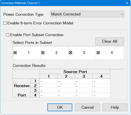
Correction Methods dialog box help


The following dialog applies to the Spectrum Analyzer applications only.
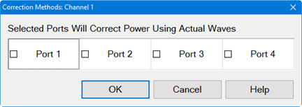
The following dialog applies to the Modulation Distortion, Modulation Distortion Converters and Intermodulation Distortion applications only.

Note: Actual Wave and 8-term error correction method in IMD/IMDX is a Licensed Feature. Learn more about Licensed Features.
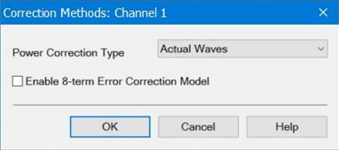
Power Wave Correction Type

Match Corrected - These waves are calculated from the actual waves and the S-parameters of the DUT to determine the waves if the VNA test ports were perfectly matched. However, you may not want match correction in the following cases:

  • When making non-traditional measurements, such as high-power or multiport configurations. Because of added components or reconfigurations, the mismatch measurement may not be valid.
  • When you have a remote program that already accounts for the match effects of the sensor.

Actual Waves - These are the full error corrected actual waves at device reference planes.

Response Corrected - These are raw measurements scaled with the response terms and do not include any match correction.

Selected Ports Will Correct Power Using Actual Waves (Spectrum Analyzer applications only) - This is the same as Match Corrected. See description above.

8-term Error Correction Model

Enable 8-term Error Correction Model - Check to enable the 8-term error correction model for measurement calibration.

The VNA may correct S-Parameters by using either the 12-term or the 8-term error correction model.  (The 12-term model is also known as the 10-Term model if the two crosstalk terms are ignored.) Changing the model will affect the S-Parameter and wave measurements.

When measuring a DUT, the VNA will stimulate the DUT in the forward and reverse direction, measure the waves, then calculate the S-Parameters of the DUT. A 2-port VNA forward flow diagram is shown below and will be used to compare the two correction models.

For an 8-term model, the forward direction state will measure the waves (a0, b0, a3, b3) and will calculate the corrected waves (a1, b1, a2, b2) at the DUT test ports. For a 12-term model, the VNA will measure the waves (a0, b0, b3) and will calculate the corrected waves (a1, b1, a2, b2) at the DUT test ports. The 12-term model does not need to measure the a3 wave because its value is calculated from the b3 wave and the Port 2 load match characterized during calibration.

The following table describes the tradeoffs between the 8-term and 12-term models:

Model

Advantages

Disadvantages

12-Term

Measures fewer waves so it may be faster and have lower noise.

VNA load match changes after calibration will result in errors.

8-Term

VNA load match changes after calibration will not result in errors.

Measures more waves so it may be slower and have higher noise.

The VNA uses the 12-term model by default because it is fast, low noise, and typically the VNA load match is very stable. However, there are several cases where the 8-term model is a good choice:

  • Load Pull measurements vary the load match to determine its effect on the DUT's S-parameters. The 8-term error model is immune to these intentional changes in VNA load match.

  • High power test setups often include external couplers, preamps, and attenuators. During calibration the preamps and attenuators may be removed to avoid damaging the cal standards and to optimize signal levels. These components are reattached following calibration. If the components are removed and added on the VNA-side of the couplers, the 8-term model will correct for any changes.

  • A preamp may be added behind the couplers of one port to increase the output power. When that port is used as the load-side of the measurement, the load match presented by the output of the preamp may not be very stable over time. The 8-term error model will correct for this load match instability.

Port subset correction

Enable Port Subset Correction - Enabling port subset correction to reduce the number of corrected ports.

Select Ports in Subset - Selects which ports should be included in a full N-port correction. Un-selected ports will be corrected on a “best effort” basis: In other words, these ports will be corrected with an enhanced response calibration if the error terms are available in the calset.

Clear All button - De-selects all ports from correction. The button will change to Select All to include all ports for correction.

To learn more about Port subset correction, go to Port Subset Correction (Devolve Calibration).

Correction Results

Correction results are displayed in this table. This is the same table displayed when the user right-clicks on the Cal pane of the status bar at the bottom of the screen. The following indicate the correction applied:

F1 - 1-port calibration.

eR - Enhanced response.

Blank - No correction applied.

F - Multiport calibration.