Straight Limit Line in Log Sweep (Line Spacing)
Other topics about Data Analysis
The limit test feature allows you to set the limit line for each trace and then perform the pass/fail judgment for the measurement result.
The limit test is a function to perform pass/fail judgment based on the limit line you set with the limit table.
In the limit test, if the upper limit or lower limit indicated by the limit line is not exceeded, the judgment result is pass; if it is exceeds, the judgment result is fail for all measurement points on the trace. Measurement points in a stimulus range with no limit line are judged as pass.
The targets of the pass/fail judgment are measurement points only. Parts interpolated between the measurement points are not judged.
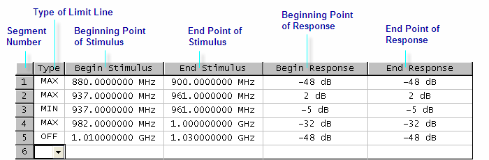
You define the limit line by specifying the stimulus value (Begin Stimulus) and response value (Begin Response) of the begin point, the stimulus value (End Stimulus) and response value (End Response) of the end point, and the type (lower limit/upper limit). For more information, refer to Defining the limit line.
When the limit test is ON, measurement points that fail are displayed in red on the screen and the trace's pass/fail judgment result based on the results of individual measurement points (fail if one or more measurement points on the trace fail) is also displayed. You can check the pass/fail judgment result for the channel (fail if one or more traces fail in any of the limit test, the ripple test or the bandwidth test within the channel) on the screen as well. For more information, refer to Displaying judgment result of limit test.
In addition to viewing the screen, you can check the judgment result of the limit test with the following methods.
Beep that occurs when the judgment result fails.
Using the status register.
Measurement points that fail are displayed in red on the screen. The judgment result of the trace is indicated by Pass or Fail displayed in the upper right section of the graph.
If a channel has a judgment result of fail, the message below appears on the screen (it will be judged as fail if one or more unsatisfactory trace exist in any of the limit test, the ripple test or the bandwidth test within the channel.)

Follow these steps to turn ON/OFF the display of the channel fail message.
Press Analysis > Limit Test.
Click Fail Sign. Each press toggles between ON/OFF.
To use the limit test, you must first define the limit line. You can define a limit table for each trace, and you can define up to 100 limit lines (segments) in a limit table.
The following steps describe how to define a segment.
Press Channel Next (or Channel Prev) and Trace Next (or Trace Prev) to select the trace on which the limit test function is used.
Press Analysis > Limit Test.
Click Edit Limit Line to display the limit table.
Using the limit table, create/edit a segment. Initially, no segments are entered in the limit table. At the same time, the Edit Limit Line menu used to create/edit the limit table is displayed.
Click Add to add a segment to the limit table and then specify the segment parameter values shown below.
|
Segment Parameter |
Description |
|
|
Type |
Select the type of segment from the following: |
|
|
OFF |
Segment not used for the limit test |
|
|
MIN |
Segment at which the minimum is specified |
|
|
MAX |
Segment at which the maximum is specified |
|
|
Begin Stimulus |
Specify starting point for stimulus value on the limit line |
|
|
End Stimulus |
Specify ending point for stimulus value on the limit line |
|
|
Begin Response |
Specify starting point for response value on the limit line |
|
|
End Response |
Specify ending point for response value on the limit line |
|
The range in which stimulus values can be specified is from -500 G to +500 G. When a value outside the range is entered, a suitable value within the range is specified. Once the stimulus value is specified, changing the sweep range of the E5061B does not affect the stimulus value.
The range in which response values can be specified is from -500 M to +500 M. When a value outside this range is entered, a suitable value within the range is specified. After the response value is specified, changing formats results in changing the units but not the value.
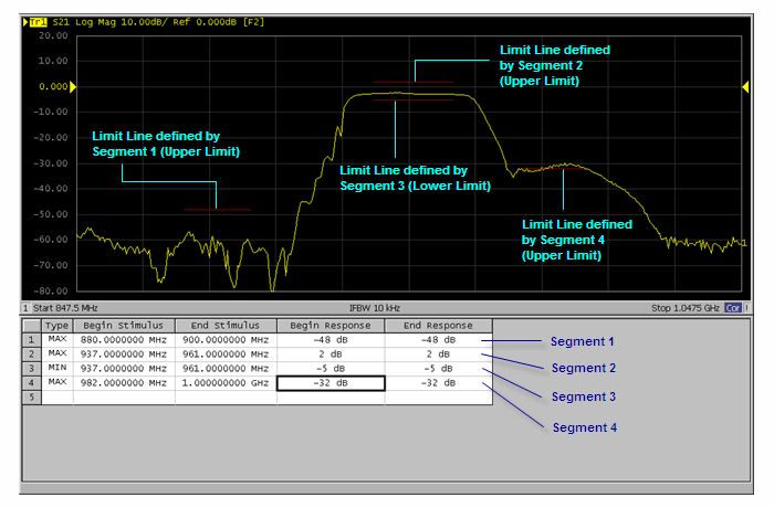
You can define a limit line that is able to freely overlap the stimulus range of another limit line.
Defining one limit line that has the same type as a second limit line whose stimulus range overlaps with the first one results in two or more limit values at the same measurement point. In this case, the limit value to be used in the limit test is defined as follows:
When two or more limit values of which the type is set to maximum (MAX) exist, the smallest one is used as the maximum.
When two or more limit values of which the type is set to minimum (MIN) exist, the largest one is used as the minimum.
Even if the span of the sweep range on the E5061B is set to 0, enter the two parameters of Begin Stimulus and End Stimulus.
When two or more response values are returned as a result of using the Smith or polar chart format, the first response value of the marker provides the object of the limit test.
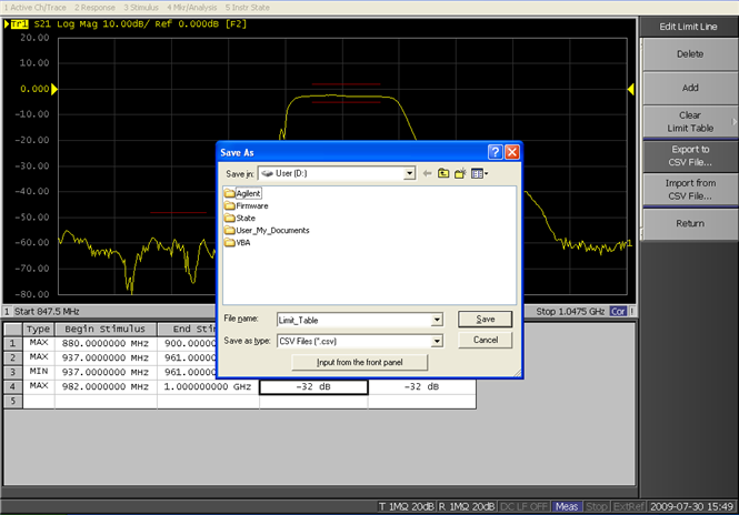
You can save the limit table to a file that you can then freely bring up on the screen later and use. You can import a file saved in CSV format (extension: *.csv) into spreadsheet software on a PC for later use (a numerical value is saved as strings that includes its unit).
Display the limit table.
In the Edit Limit Line menu, press Export to CSV File to open the Save As dialog box. In this step, CSV (extension: *.csv) is selected as the file type.
Specify the folder in which to save the file and enter the file name. Press Save to save the limit table displayed on the screen to the file.
Conversely, to recall a saved limit table, press Import from CSV File in the Edit Limit Line menu to display the Open dialog box. In this step, CSV (extension: *.csv) is selected as the file type.
After specifying the folder containing the file, select the file. Press Open to display the limit table on the screen.
The limit table can be called from any trace of any channel, regardless of the channel or trace.
The limit table is saved in the following format.
On the first line, the channel number of the active channel that is valid when the saved file is the output.
On the second line, the trace number of the active trace that is valid when the saved file is the output.
The third line provides the header showing the items for the segments to be output on the fourth and later lines.
Data on segments are output on the fourth and later lines.
"# Channel 1"
"# Trace 1"
Type, Begin Stimulus, End Stimulus, Begin Response, End Response
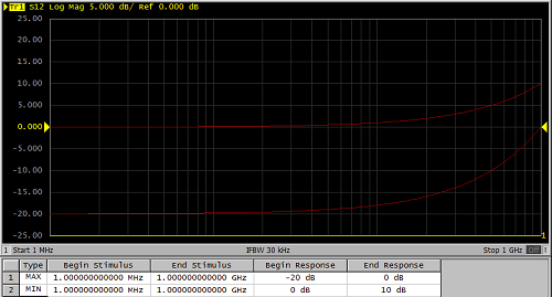
MAX, 200.0000000 MHz, 400.0000000 MHz, -100 dB, -100 dB
MAX, 490.0000000 MHz, 510.0000000 MHz, -10 dB, -10 dB
MIN, 490.0000000 MHz, 510.0000000 MHz, -20 dB, -20 dB
MIN, 600.0000000 MHz, 800.0000000 MHz, -100 dB, -100 dB
You can set the limit test ON/OFF for each trace individually.
Press Channel Next (or Channel Prev) and Trace Next (or Trace Prev) to select the trace on which the limit test function is used.
Press Analysis > Limit Test to display the Limit Test menu.
Press Limit Test to set the limit test ON/OFF.
Press Limit Line to set the limit line display ON/OFF.
You can specify the limit line display mode hide limit values that are not used for evaluation.
Changing the display mode:
Press Channel Next (or Channel Prev) and Trace Next (or Trace Prev) to activate the channel of which you want to use the limit test function.
Press Analysis > Limit Test.
Turn off Limit Line.
Press Clip Lines to toggle ON/OFFf.
Limit line display mode
If the shape is more important than the amplitude, you can make the limit lines relative to the peak point of the trace using the reference tracking function.
In this function, the point to be tracked is set as the Y-axis reference value by offsetting measurement values after the sweep. Because measurement values are offset, marker values and limit test evaluation results change accordingly.
Press Channel Next (or Channel Prev) and Trace Next (or Trace Prev) to select the channel/trace.
Press Scale > Reference Tracking.
When you want to specify a measurement value at a frequency as the Y-axis reference value for tracking, press Track Frequency, then enter the frequency.
Press Tracking to select a tracking method.
PTrk (Track Peak) or FTrk (Frequency) is displayed at the trace status area.
This function is available even when the limit test function is off.
By adding a certain offset to the limit value, you can adjust the limit line so that it conforms to the device output.
Press Channel Next (or Channel Prev) and Trace Next (or Trace Prev) to select the channel/trace on which the limit test function is used.
Press Analysis > Limit Test to display the softkeys for the limit test.
Click Limit Line Offsets to display the limit line offset function menu.
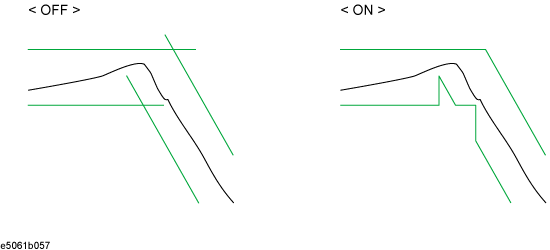
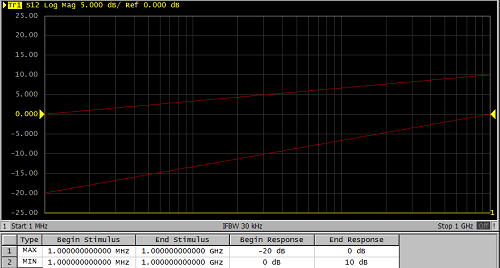
A straight limit line can be applied even in log sweep or log scale. This function is available at B.05.xx and above.
Press Channel Next (or Channel Prev) and Trace Next (or Trace Prev) to select the channel/trace on which the limit test function is used.
Press Analysis > Limit Test to display the softkeys for the limit test.
Click Line Spacing to select from two.
Linear: Limit Lines are drawn based on linear x-y axis. The ramp limit line looks an exponential curve once you set the x or y axis at logarithmic.
Display: Limit lines are drawn by a straight line on the display. If x and/or y axes are logarithmic, the limit line is calculated correspondingly, so the ramp limit line looks straight line.
Linear: Limit Line is an exponential in log sweep.
Display: Limit Line is straight line in log sweep.
The following operations initialize the limit table.
At power-on
When presetting
When calling a limit table with zero segments
When Clear Limit Table > OK is pressed in the Edit Limit Line menu