This section describes the concept of the segment sweep and how to perform it.
Other topics about Optimizing Measurements
To perform a segment sweep, you must define two or more frequency ranges, called segments, and then specify the number of points, IF bandwidth, power level, sweep delay time, and sweep time for each segment. All segments are swept sequentially as if swept in one sweep operation.
By skipping the frequency range, which does not need to be measured, you can sweep and measure only the portions you need.
You can define the optimum measurement conditions for each of the segments you designate. For example, you can specify as many points as possible in a segment requiring high trace resolution and as few points as possible in a segment not requiring high resolution. This shortens the measurement time, enabling you to optimize the overall measurement throughput by not having to perform the entire operation under the same measurement conditions of a particular frequency range.
To evaluate a band pass filter that has the transmission characteristics shown in the following figure, for example, you can select the frequency ranges you need from A through G and determine the measurement conditions shown in the table below. This enables you to measure them simultaneously in one sweep operation.
|
Frequency ranges (segments) from the figure above and their measurement conditions |
||||
|
|
Start frequency |
Stop frequency |
Number of points |
IF Bandwidth |
|
A |
440 MHz |
915 MHz |
50 |
50 kHz |
|
B |
915 MHz |
980 MHz |
130 |
70 kHz |
|
C |
980 MHz |
1.035 GHz |
60 |
50 kHz |
|
E |
1.07 GHz |
2 GHz |
100 |
70 kHz |
|
G |
2.6 GHz |
3 GHz |
40 |
70 kHz |
The following conditions apply in setting up a segment sweep.
The frequency range of a segment must not overlap with that of another segment. (The start frequency of a segment must be higher than the stop frequency of the immediately preceding segment).
The start frequency of segment 1 must be greater than 5 Hz and the stop frequency of the last segment less than 3 GHz, as per the range of the Network Analyzer.
When the start frequency and stop frequency of a segment are not the same, you can define from 2 to the maximum points in a segment.
When the start frequency and stop frequency of a segment are the same, you can define from 1 to the maximum points in a segment.
You can set the total number of points in the segment table from 2 to the maximum points.
You can set the number of segments in the segment table to between 1 and 201.
For the segment sweep, you can set the sweep range, the number of points, IF bandwidth, power level, sweep delay time, and sweep time for each segment.
You can set the items in the following table to ON/OFF for each segment. If you enable the segment-by-segment setting, you can make the setting for each segment in the segment table; if you disable it, the setting in the following table is used.
|
Item |
When segment-by-segment setting is disabled |
|
IF bandwidth |
For all segments, the IF bandwidth (set with Avg > IF Bandwidth) is set even if IFBW AUTO is turned ON. |
|
Power level |
For all segments, the power level for the linear/log sweep (set with Sweep Setup > Power) is set. |
|
Sweep delay time |
For all segments, 0 is set. |
|
Sweep time |
For all segments, the auto sweep time mode is set. |
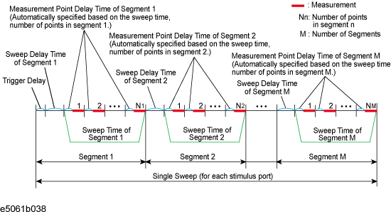
The definitions for sweep delay time and sweep time, which you can specify in the segment sweep, are shown in below figures.
The definitions for sweep delay time and sweep time when trigger mode is "On Sweep".
The definitions for sweep delay time and sweep time when trigger mode is "On Point".
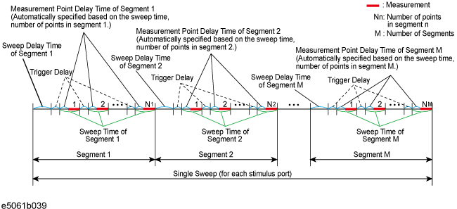
The segment trigger delay is not included in the segment sweep time.
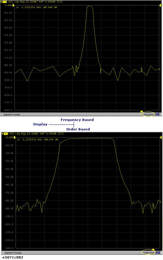
You can choose between frequency-based and order-based display as the method of displaying traces when executing a segment sweep.
Press Channel Next (or Channel Prev) to select the channel of which you want to create the segment table.
Press Sweep Setup.
Click Edit Segment Table. The segment table appears in the lower section of the screen.
Select the softkey to change the frequency range setting mode or to set the IF bandwidth, power level, sweep delay time, and sweep time for each segment.
When setting the segment table using the front panel keys or keyboard, you need to place focus on (select) the operation target (segment table of softkey) first. You can change the focus by pressing Foc key in the ENTRY Block. When the focus is placed on the segment table, the window frame of the segment table is displayed as bright as the window frame of the active channel. When the focus is placed on the softkey menu, the softkey menu title area is displayed in blue.
Enter each item in the following table for each added segment (line) to create the segment table. To create the segment table, use the hardkeys and softkeys.
|
Start |
Sets the start value of the sweep range |
|
Stop |
Sets the stop value of the sweep range |
|
Center |
Sets the center value of the sweep range |
|
Span |
Sets the span value of the sweep range |
|
Points |
Sets the number of points |
|
IFBW |
Sets the IF bandwidth |
|
Power |
Sets the power level; the power range is common to the settings for the linear/log sweep (Sweep Setup > Power Ranges) |
|
Delay |
Sets the sweep delay time |
|
Time |
Sets the sweep time; to specify the auto setting (AUTO), enter 0 as the sweep time |
You can copy/paste/insert/delete the cell by right-clicking on the selected cell.
In the character-by-character edit mode, you can undo/cut/copy/paste/delete/select all by right-clicking in the cell.
To execute a segment sweep by using the segment table you have created, you must specify the sweep type for that sweep operation by following the steps below.
Press Channel Next (or Channel Prev) to select the channel on which you execute the segment sweep operation.
Press Sweep Setup > Sweep Type > Segment.
Define the method of displaying traces when the segment sweep is executed by following the steps described below.
Press Channel Next (or Channel Prev) to select the channel on which you define the segment display.
Press Sweep Setup > Segment Display.
Select the segment display.
As discussed in Creating a segment table, you can export the newly created segment table as a CSV (comma-separated value) formatted file (so it can be used easily in software that requires a different format).
Press Sweep Setup.
Click Edit Segment Table > Export to CSV File to open the Save As dialog box. Note that CSV files (*.csv) is already selected as the file type when the dialog box first opens.
Type the file name in the File Name area and Click Save to save the segment table.
By importing a segment table file saved by E5061B, you can set up the segment table.
It is possible to recall a file from a different channel where it is saved.
Press Sweep Setup.
Click Edit Segment Table > Import from CSV File to open the Open dialog box. Note that CSV files (*.csv) is already selected as the file type when the dialog box first opens.
Select the CSV format file to be imported, and click Open to call up the segment table.
You cannot import a CSV-formatted file created/edited in spreadsheet software into the E5061B.