This application is a tool to calculate the parameter related with wireless power transfer from S-parameter measurement of network analysis. This does not provide an error free measurement and not guarantee the measurement accuracy.
This application calculates the parameter related with wireless power transfer from S-parameter measurement of network analysis. The measurement result may include the error of S-parameter measurement. Users should consider to eliminate the measurement error.
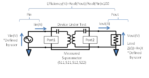
The Wireless Power Transfer (WPT) analysis application (Option 006) converts 50 Ω based S-parameters measurements to Voltage, Current, Power and Efficiency of the voltage driving circuit with arbitrary load impedance. These key parameters for WPT circuit design are displayed on display in real-time.
Parameters specified by the user are the voltage value applied to DUT (Vin) and, Load impedance connected to the output (Z = R + jX).
This application performs calculations and displays the results of measurement on the assumption that the load and voltage source is connected with a DUT.
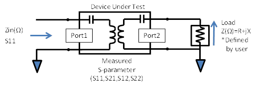
When the Zin (Ohm), S11 are selected as Set Trace, the calculation is performed under assumption of the following circuit. This application calculates the impedance Zin (Ω) which is viewed from the Port1 side when the port 2 is terminated with R+jX, not 50 Ω. This also calculates the reflection coefficient S11 at the 50Ω system which is viewed from the Port1 side when the port 2 is terminated with R+jX.
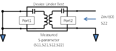
When the Zout (Ohm), S22 are selected as Set Trace, the calculation is performed under assumption of the following circuit. This calculates the impedance Zout (Ω) which is viewed from the Port2 side when the port 1 is terminated with short 0 Ω, not 50 Ω. This also calculates the reflection coefficient S22 at the 50Ω system which is viewed from the Port2 side when the port 1 is terminated with short 0 Ω.
There are two modes for the display of analysis, mode-1 and -2.
Mode-1: Real-time analysis
Default mode after the start-up. Display real-time measurement results including power transfer efficiency(%). Other parameters such as Zin, Zout, S11, S22 are available. Load impedance, R and X, can be defined by user.
Mode-2: 2D/3D simulation
Displays simulated results sweeping one (2D) or two (3D) of the three parameters (Load R, Load X, Frequency). The measurement result in Mode-1 is used for simulation. It’s useful for evaluation of the dependency to the Load impedance.
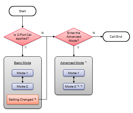
Basic Mode
2-Port Cal is required in advance of the WPT application launch. Perform 2 Port Calibration at the end of coaxial test cables. Then, connect the DUT to the test cables. Do not change any settings in the Basic Mode. If you change any settings, the software will require you to go to the Advanced Mode, or will be stopped.
Advanced Mode
2-Port Cal is not required in advance of the application launch. You can change any settings in the Advanced Mode, however, the measurement performance is not guaranteed in this mode.
The following picture shows the transition between Basic and Advanced modes.
|
|
Basic Mode |
Advanced Mode*1 |
|
Calibration in advance of the application launch |
2 port cal is required |
Not required |
|
Setting change after application launch *2 |
Not allowed |
Allowed |