Measurement Example of a Ceramic Resonator
(Gain-Phase/Series-Through)
This section describes how to measure the frequency characteristics of a ceramic resonator using the Series-Through method on Gain-Phase ports using Keysight test fixture. You can connect Keysight 4 terminal pair type fixture on the Gain-Phase ports.
In this example, the following items are used.
|
|
|
|
|
Test Fixture
|
Keysight 16047E
|
-
|
|
Shorting Bar
|
16047-00621
|
Furnished with the 16047E
|
|
Leaded Load
|
5012-8646
|
50 Ω leaded resister. Furnished with E5061B option 720.
|
|
DUT
|
Ceramic resonator
|
-
|
To measure another device under test (DUT), change the measurement conditions to suit the particular DUT.
STEP 1. Determining Measurement Conditions
-
Preset the E5061B.
Preset > OK
-
Set the number of traces at two and display each trace in one frame.
Display > Num of Traces > 2
Display > Allocate Traces > x2 
-
Set the measurement port to Gain-Phase.
Meas > Measurement Port > Gain-Phase
-
Set the method to Series-Through configuration.
Meas > Impedance Analysis Menu > Method > GP Series T 50Ω, R 1MΩ
-
Set the measurement parameter at |Z| for the trace 1 and θ type of each trace.
Select Trace 1 as the active trace. Meas > Impedance Analysis Menu > |Z|
Select Trace 2 as the active trace. Meas > Impedance Analysis Menu > θz
-
Specify the center and span frequencies to observe the frequency characteristic. In this example, the center is set at 395 kHz and span is set at 40 kHz.
Center > 3 > 9 > 5 > k/m
Span > 4 > 0 > k/m
-
When entering the frequency unit using the keyboard, type "G" for GHz, "M" for MHz, and "k" for kHz.
-
Set the power level at 0 dBm (224 mV @ 50 Ω).
Sweep Setup > Power > 0 > x1
-
Set the sweep type at Linear.
Sweep Setup > Sweep Type > Lin Freq
-
Set the IF bandwidth at AUTO.
Avg > IF BW Auto .
-
Set the IFBW auto limit at 100 Hz.
Avg > IFBW Auto Limit > 1 > 0 > 0 > x1
STEP 2. Calibration
-
Select the calibration kit for leaded 50 Ω.
Cal > Cal Kit > Leaded 50ohm
-
Connect Keysight 16047E test fixture on the ports R, T and LF Out.
-
Set the open state of the 16047E.
-
Measure the calibration data for open.
Cal > Calibrate > Impedance Calibration > Open
-
Set the short bar on the 16047E.
-
Measure the calibration data for short.
Short
-
Set the load on the 16047E.
-
Measure the calibration data for load.
Load
-
Finalize the calibration measurement. The calibration factor is calculated based on the calibration data acquired, and the error correction is turned ON. Cor is displayed at the bottom of the channel window.
Done
STEP 3. Connecting the Device Under Test (DUT)
-
Set the ceramic resonator on the 16047E.
-
Set the log scale for Trace 1.
Select Trace 1 as the active trace. Scale > Y-Axis > Log
-
Set the appropriate scale for both traces by executing the auto scale.
Scale > Auto Scale All
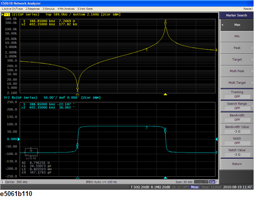
STEP 4. Analyzing Measurement Results
This section describes how to use the marker function to read out the resonant point and the Equivalent circuit analysis.
Reading the values of resonant points
-
Display a marker.
Marker > Marker 1
-
Search the minimum point.
Marker Search > Min
Reading the values of anti-resonant points
-
Display a second marker.
Marker > Marker 2
-
Search the maximum point.
Marker Search > Max
Using Equivalent Circuit Analysis
-
Select the Equivalent circuit model.
Analysis > Equivalent Circuit > Select Circuit > E.
-
Turn the Equivalent Circuit Display ON.
Analysis > Equivalent Circuit > Display
-
Calculate each parameter of the circuit model.
Calculate. The calculated parameters are displayed in each box of R1, C1 and L1.
-
You can simulate the frequency characteristics by using the approximate value obtained from the above calculation.
Analysis > Equivalent Circuit > Simulate
Measurement Result