Measurement Example of a Capacitor (Port 1-2/Shunt-Through)
This section describes how to measure the frequency characteristics of a capacitor using the Series-Through method on ports 1 and 2.
In this example, the following items are used.
|
|
|
|
|
Test Fixture with DUT (Capacitor)
|
PC board user fixture
|
-
|
|
Test Fixture with Open or Short
|
PC board user fixture
|
-
|
|
Calibration Kit
|
85033E
|
Mechanical Calibration Kit, DC to 9 GHz, 3.5 mm
|
|
Cable and Adapter
|
Cables and adapters for Type-N or 3.5 mm
|
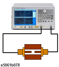
Connect your PC board to ports 1 and 2 of the E5061B
|
To measure another device under test (DUT), change the measurement conditions to suit the particular DUT.
STEP 1. Determining Measurement Conditions
-
Preset the E5061B.
Preset > OK
-
Set the number of traces at two and display each trace in one frame.
Display > Num of Traces > 2
Display > Allocate Traces > x2 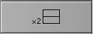
-
Set the measurement port to Gain-Phase.
Meas > Measurement Port > S-Parameter
-
Set the method to Port 1-2 Shunt-Through configuration.
Meas > Impedance Analysis Menu > Method > Port 1-2 Shunt
-
Set the measurement parameter at |Z| for the trace 1 and θ type of each trace.
Select Trace 1 as the active trace. Meas > Impedance Analysis Menu > |Z|
Select Trace 2 as the active trace. Meas > Impedance Analysis Menu > θz
-
Specify the center and span frequencies to observe the frequency characteristic. In this example, the start is set at 100 kHz and stop is set at 1 GHz
Start > 1 > 0 > 0 > k/m
Stop > 1 > G/n
-
When entering the frequency unit using the keyboard, type "G" for GHz, "M" for MHz, and "k" for kHz.
-
Set the power level at 0 dBm (224 mV @ 50 Ω).
Sweep Setup > Power > 0 > x1
-
Set the sweep type at Log.
Sweep Setup > Sweep Type > Log Freq
-
Set the IF Bandwidth at 100 Hz.
Avg > IF Bandwidth > 1 > 0 > 0 > x1
STEP 2. Calibration
-
Select the calibration kit for 85033E.
Cal > Cal Kit > 85033E
-
Connect the two 3.5 mm cables on both ports 1 and 2.
-
Perform Full 2-Port Calibration at the end of each cables.
-
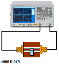
Connect the fixture with open (or short) between the cables.
-
Perform Auto Port Extension.
STEP 3. Connecting the Device Under Test (DUT)
-
Connect the fixture with DUT between the cables instead of the fixture, with open (or short).
-
Set the log scale for Trace 1.
Select Trace 1 as the active trace. Scale > Y-Axis > Log
-
Set the appropriate scale for both traces by executing the auto scale.
Scale > Auto Scale All
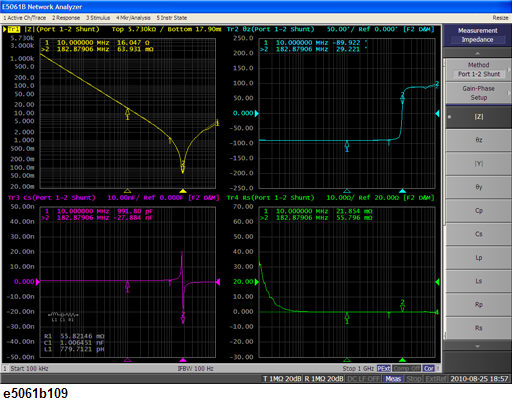
STEP 4. Analyzing Measurement Results
This section describes how to use the Equivalent circuit analysis.
Using Equivalent Circuit Analysis
-
Select the Equivalent circuit model.
Analysis > Equivalent Circuit > Select Circuit > E.
-
Turn the Equivalent Circuit Display ON.
Analysis > Equivalent Circuit > Display
-
Calculate each parameter of the circuit model.
Calculate. The calculated parameters are displayed in each box of R1, C1 and L1.
-
You can simulate the frequency characteristics by using the approximate value obtained from the above calculation.
Analysis > Equivalent Circuit > Simulate
Measurement Result