Other topics about Impedance Measurement Quick Start
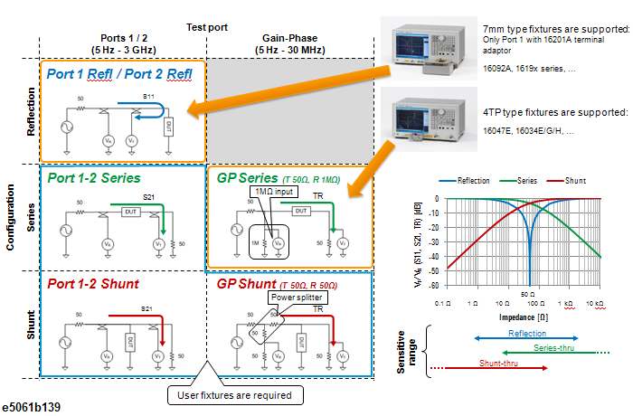
This section describes the impedance measurement method. Five methods shown in the following table can be used to make an impedance measurement. For the connection for each method, see Preparation for Measurement.
When you select Impedance (Meas > Impedance Analysis Menu) as the Measurement type, the measurement method is made available (Meas > Impedance Analysis Menu >Method).
The characteristics of the measurement method is as described in the following table:
|
Method |
Port 1 (or 2) Reflection |
Port 1-2 Series |
Port 1-2 Shunt |
GP Series |
GP Shunt |
|
Measurement DUT Impedance Range |
Low to middle impedance |
Middle to high impedance in the high frequency range Not applicable to grounded DUTs |
Very low impedance in the high frequency range |
Middle to high impedance in the low frequency range |
Very low impedance in the low frequency range |
|
Formula |
Zdut = 50 x (1+S11)/(1-S11) |
Zdut = 50 x 2 x (1-S21)/S21 |
Zdut = 50 x S21/(2 x (1-S21)) |
Zdut = 50 x (1-TR)/TR |
Zdut = 50 x TR/(2 x (1-TR)) |
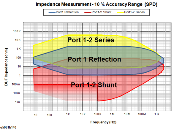
The following figures show the 10% accuracy range for each method. You can select the appropriate method according to your DUT impedance.
The following table shows the condition where the 10% measurement accuracy range shown above is specified.
|
Method |
Frequency |
Calibration |
IFBW |
Source Power |
Note |
||||||
|
Port 1-2 Series |
5 Hz to 3 GHz
|
Full 2-port calibration at measurement terminals of fixture or Full 2-port calibration + Open/Short/Load fixture compensation Note Without a Full 2-port calibration or Open/Short/Load fixture compensation at terminals of fixture, measurement accuracy may be degraded by a mismatch at RF range (≥ 500 MHz) |
See the following table
|
-20 to 0 dBm |
|
||||||
|
Port 1 Reflection |
Impedance calibration: Open/Short/Load at 7 mm terminal of the 16201A. Calibration kit: 16195B or 85031B |
||||||||||
|
Port 1-2 Shunt |
100 kHz to 3 GHz |
Impedance calibration: Open/Short/Load Note Without a Full 2-port calibration or an impedance calibration (Open/Short/Load) at DUT connection terminal, a measurement accuracy may be degraded by a mismatch above 500 MHz. |
10 Hz |
10 dBm |
Measurement error in the short calibration is included. (10 pH residual inductance of short standard is included.) A ferrite core is required to measure DUTs with 100 mΩ or below at ≤100 KHz. |
23±5 °C at calibration
(calibration temperature) ±1 °C at measurement
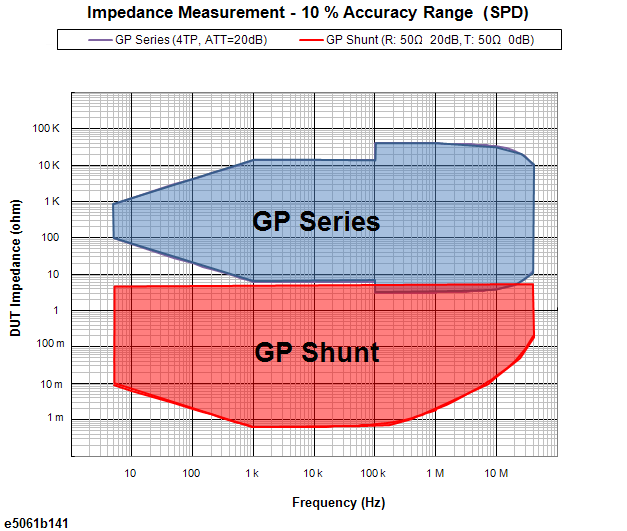
The following table shows the condition where the 10% measurement accuracy range shown above is specified.
|
Method |
Frequency |
Calibration |
Receiver Setup |
IFBW |
Source Power |
Note |
||||||
|
GP Series |
5 Hz to 30 MHz |
Open/Short/Load calibration at measurement terminals of fixture Fixture: 16047E or 16034E/G/H
|
Rch: Tch: |
See the following table
|
-20 to 0 dBm |
Only with the response-thru calibration at the terminals of fixture, the measurement accuracy may be degraded due to a parasitic capacitance of receiver port at RF range (≥1 MHz) |
||||||
|
GP Shunt |
Open/Short/Load calibration at measurement terminals of fixture (Source=-10 dBm at calibration) Note Only with the response-thru calibration at the terminals of fixture, the measurement accuracy may be degraded by a parasitic capacitance of receiver port at RF range (≥ 1 MHz).
|
Rch: Tch: |
See the following table
|
10 dBm |
Measurement error in the short calibration is included (10 pH residual inductance of short standard is included.) Maximum DUT impedance is 5 Ω in this condition in order to avoid a receiver saturation |
23±5 °C at calibration
(calibration temperature) ±1 °C at measurement
The following figure shows the configuration for each method.