Adapter Removal
Adapter Insertion
Difference between Traditional Network Analyzer & E5063A Adapter Calibration
Other topics about Advanced Calibration
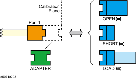
Adapter Removal is a technique used to remove any adapter characteristics from the calibration plane. The E5063A uses the following adapter removal process to remove the adapter characteristics:
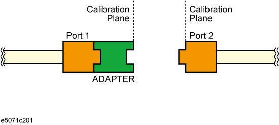
Perform calibration with the adapter in use.
Remove the adapter from the port and measure Open, Short, and Load values to determine the adapter's characteristics.
Remove the obtained adapter characteristics from the error coefficients in a de-embedding fashion.
Open, Short, and Load values measured with the adapter removed
The adapter removal and partial overwrite function is only available when the calibration status is [Cor] and not for [C?] or [C!].
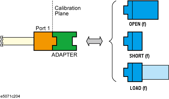
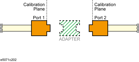
The above described method also makes it possible to add adapter characteristics to a port with n-port full calibration. This allows you to make a measurement with the adapter. E5063A uses the following adapter insertion process to insert the adapter characteristics:
Perform calibration without adapter in use.
Insert the adapter to the port and measure Open, Short, and Load values to determine the adapter's characteristics.
Insert the obtained adapter characteristics to the error coefficients in an embedding fashion.
Open, Short, and Load values measured with adapter attached
In order to determine the adapter characteristics (with four unknown parameters) by making three measurements (Open, Short, and Load), the adapter must satisfy the following requirements:
Adapter must be Reciprocal (with S21 and S12 equal) in nature. It should have a consistent behavior, and independent of the direction from which it is used.
The electrical length of the adapter should be known with the accuracy of ±1/4 of wavelength.
E5063A has the functionality related to adapter waveguide and adapter rotation. Adapter waveguide length and Cut off frequency can be set using the following commands:
Coaxial length can be set using Cal > Calibrate > Adapter Removal > Coaxial Length
Rotate command executes Adapter Removal/Insertion along with moving the phase of adapter (which is removed or inserted) to 180 degrees. This command is useful in cases where auto judgement of phase fails. This command can be executed several times while the calibration remains valid.
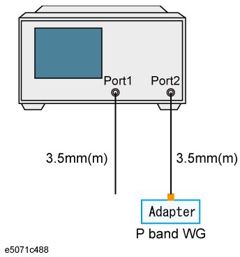
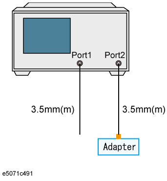
This section provides an example of performing adapter waveguide calibration to perform a Full 2-port calibration plane between Port 1 (3.5mm) & Port 2 (P-band wave guide).
Using Adapter Insertion:
Perform a SOLT F2P Calibration at Port 1 (3.5mm) using Z0=50 ohm
Perform Adapter insertion at Port 2 (Z0=1) using P11644A

Using Adaptor Removal:
Perform a SOLT/TRL F2P Calibration at P band WG (Z0 = 1)
Perform Adapter removal at port 1 (Z0=50) using 85052D
Using Port Extension:
Perform a SOLT F2P calibration at Port 1 (3.5mm) with Z0 = 50
Perform Port extension calibration at Port 2 (manual with Coax length, WG length, Cut off). System Z0 can be either 1 oh or 50 ohm; both are fine to use.
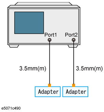
Example of scenario where adapter removal/insertion is required: When the DUT is an SMA (female) -to-Type N (male) whereas the test ports are two SMA (male) cables. In such cases, an adapter of Type N (female)-to-SMA (female) is required to perform adapter removal/insertion.
The S parameter of a reciprocal adapter can be determined when the following data is available:
Open, Short, and Load measurements.
Actual values derived from the CalKit definitions.
An approximate length of the adapter.
Nature of the intended operation: removal or insertion.
If the frequency setting is not Zero Span, an approximate length of the adapter should be provided otherwise an error might be generated in the measurement.
For Adapter Removal, the adapter length is (+) Positive. For Adapter Insertion, the Adapter length is (-) Negative.
The diagram below shows summary of the adapter removal and insertion procedure:
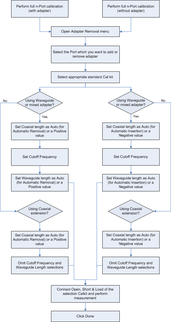
Perform a full n-Port calibration using your calibration kit so that the port used to conduct adapter removal is calibrated.
When you need to remove an adapter from the calibration plane (adapter removal) to connect your DUT, perform the calibration with an adapter so that you can make a calibration with your calibration kit.
Open the Adapter Removal menu: Cal > Calibrate > Adapter Removal.
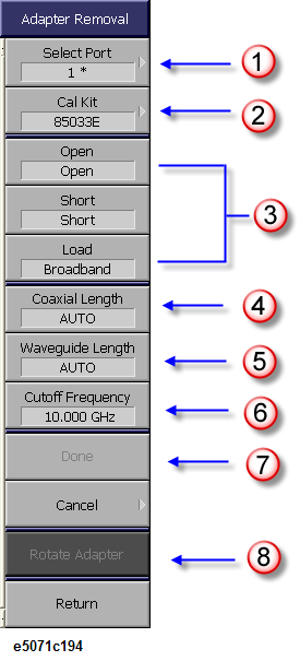
Select the Port from which you want to remove Adapter characteristics from. Select Port (e.g. 1) (1 in the above figure). A * sign appears in front of the port indicates that this is a valid port to conduct adapter removal (as well as insertion) as the full n-port calibration has been performed on the port.
Select the proper standard Calkit you need to use from the options available at CalKit (e.g. 85033E) (2 in the above figure) to characterize the adapter. The calibration kit is used at the plane from which adapter is removed.
If you are using a Waveguide or a mixed adapter:
Set the Coaxial length as Auto for Automatic Removal or with a (+) Positive value.
Select the Cutoff Frequency of the waveguide you want to enter (6 in the above figure). The Cutoff Frequency is defined by the waveguide calibration kit in use.
Without entering the value of Cutoff Frequency, the Waveguide Length cannot be entered.
Set the Waveguide Length as Auto for Automatic Removal or if you want to input a manual Waveguide Length, type a value with a (+) Positive value, which indicates removal.
If you are using Coaxial extension:
Set the Coaxial length as Auto for Automatic Removal or with a (+) Positive value.
Omit the Cutoff Frequency and Waveguide Length selection.
Connect Open, Short, and Load of the selected Calkit (e.g. 85033E) with the selected port respectively and click/press Open, Short, and Load respectively. E5063A measures the cal kit standard, calculates the adapter characteristics, and then conducts adapter removal/insertion.
A checkmark ![]() appears in (Open, Short, and Load) menu after each type of calibration is completed.
appears in (Open, Short, and Load) menu after each type of calibration is completed.
Click Done to complete the process (7 in the above figure).
Some calibration kits such as the waveguide calibration kit have operational frequency range defined by Minimum and Maximum frequency. When the E5063A stimulus setting is out of the operational frequency range, you cannot click Done or finish the calibration by remote control. In this case, use a calibration kit that has proper frequency range, or change the E5063A stimulus setting to proper range that the calibration kit can cover. Refer to the calibration kit manual or definition in the E5063A with Cal > Modify Cal Kit > Define STDs for the Maximum & Minimum frequency of the calibration kit.
In cases where auto judgement of phase fails, select Rotate Adapter to move the phase of adapter (which is removed) to 180 degrees.
Perform a full n-Port calibration using your calibration kit so that the port used to conduct adapter insertion is calibrated.
When you need to add an adapter into the calibration plane (adapter insertion) to connect your DUT, perform the calibration without an adapter.
Open the Adapter Removal menu:
Cal > Calibrate > Adapter Removal
Select the Port in which you want to insert the Adapter characteristics from Select Port (e.g. 1) (1 in the above figure. A * sign appears in front of the port is a valid port to conduct adapter insertion (as well as removal) as the full n-port calibration has been performed on the port.
Select the proper standard Calkit you need to use from the options available at CalKit (e.g. 85033E) (2 in the above figure) to characterize the adapter. The calibration kit is used at the plane in which adapter is inserted.
If you are using a Waveguide or a mixed adapter:
Set the Coaxial length as Auto for Automatic Insertion or with a (-) Negative value.
Select the Cutoff Frequency of the waveguide you want to enter (6 in the above figure). The Cutoff Frequency is defined by the waveguide calibration kit in use.
Without entering the value of Cutoff Frequency, the Waveguide Length cannot be entered.
Set the Waveguide Length as Auto for Automatic Insertion or if you want to input a manual Waveguide Length, type a value with a (-) Negative value, which indicates insertion.
When using waveguide calibration kit and measuring waveguide devices, ensure that you change the system Z0 to 1 ohm prior to calibration.
If you are using Coaxial extension:
Set the Coaxial length as Auto for Automatic Insertion or with a (-) Negative value.
Omit the Cutoff Frequency and Waveguide Length selection.
Connect Open, Short, and Load of the selected Calkit (e.g. 85033E)with the selected port respectively and select Open, Short, and Load respectively. ENA measures the cal kit standard, calculates the adapter characteristics, and then conducts adapter insertion.
A checkmark ![]() appears in (Open, Short, and Load) menu after each type of calibration is completed, respectively.
appears in (Open, Short, and Load) menu after each type of calibration is completed, respectively.
Click Done to complete the process (7 in the above figure).
Some calibration kits such as the waveguide calibration kit have operational frequency range defined by Minimum and Maximum frequency. When the E5063A stimulus setting is out of the operational frequency range, you cannot click Done or finish the calibration by remote control. In this case, use a calibration kit that has proper frequency range, or change the E5063A stimulus setting to proper range that the calibration kit can cover. Refer to the calibration kit manual or definition in the E5063A with Cal > Modify Cal Kit > Define STDs for the Maximum & Minimum frequency of the calibration kit.
In cases where auto judgement of phase fails, select Rotate Adapter to move the phase of adapter (which is inserted) to 180 degrees.
Usually, two-port network analyzers remove the adapter characteristics by performing two sets of Full 2 Port Calibration as shown below:
Calibration performed with the adapter connected to Port2
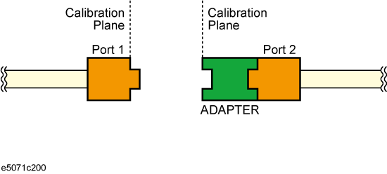
Calibration performed with the adapter connected to Port1
Removing adapter characteristics using two (above) sets of calibration
However, this method is not suitable for a multi-port network analyzer because it requires Full 2 Port Calibration as many as twice the number of port combinations. Therefore, the E5063A uses an advanced method to remove the Adapter characteristics described in About Adapter Insertion.