Other topics about Setting Measurement Conditions
The auto scale function is used to tailor each scale (scale/division and the reference line value) automatically in such a way that traces will appear at the proper size on the screen for easy observation.
The scale data can be preset to factory settings using the Preset option.
Follow the procedure below to perform the auto scale function on a specific trace.
Press Channel Next/Channel Prev keys and Trace Next/Trace prev keys to select the trace for which the auto scale function will be performed.
Press Scale > Auto Scale.
Auto Scale on All Traces Within a Channel
Press Channel Next/Channel Prev keys to select the channel for which the auto scale function will be performed.
Press Scale > Auto Scale.
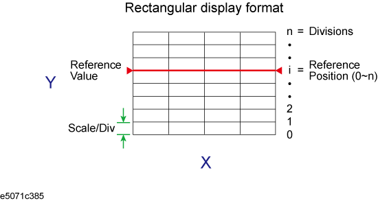
For a rectangular display format, four parameters are used to manually adjust the scales.
|
Adjustable feature |
Description |
|
Divisions |
Defines the number of divisions on the Y-axis. An even number from 4 to 30 must be used. Once set, it is commonly applied to all traces displayed in any rectangular format within that channel. |
|
Scale/Division (Scale/Div) |
Defines the number of increments per division on the Y-axis. The value applies only to the active trace. |
|
Reference position |
Defines the position of the reference line. The position must be specified using the number assigned to each division on the Y-axis starting at 0 (the least significant) running up to the number of divisions being used (the most significant). The position applies only to the active trace. |
|
Reference line value (Reference Value) |
Defines the value corresponding to the reference line. It must be set using the unit on the Y-axis. The reference line value applies only to the active trace. |

Press Channel Next/Channel Prev keys and Trace Next/Trace prev keys to select the trace for which scale features will be adjusted.
Press Scale key.
Select the softkey that corresponds to the particular feature that needs to be adjusted.
|
Softkey |
Function |
|
Divisions |
Defines the number of divisions on the Y-axis. |
|
Scale/Div |
Defines the number of increments per division on the Y-axis. |
|
Reference Position |
Defines the position of the reference line. |
|
Reference Value |
Defines the value corresponding to the reference line. |
It is also possible to turn off the display of graticule labels. For details, refer to Turning_off_the_display_of_graticule_labels.
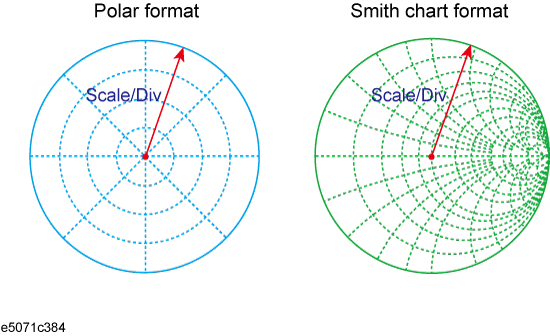
Manual scale adjustment on the Smith chart format or the polar format is done by using the displacement (Scale/Div of the outermost circle).

Press Channel Next/Channel Prev keys and Trace Next/Trace prev keys to select the trace for which the scale will be adjusted.
Press Scale key.
Click Scale/Div, then input the displacement of the outermost circle.
When using a rectangular display format, it is possible to change the reference line value to be equal to the response value of the active marker on the active trace.
Place the active marker on the active trace on the position that corresponds to the new reference line value.
Press Scale or Marker Fctn key.
Click Marker -> Reference to change the reference line value to the marker response value.
If the reference marker is on and the stimulus value of the active marker is expressed using a value relative to the reference marker, the absolute stimulus value will be used to set the new reference line value.