The E5072A allows you to evaluate the DUT (device under test) characteristics by using the following measurement parameters.
Other topics about Setting Measurement Conditions
Press Channel Next (or Channel Prev) and Trace Next (or Trace Prev) to select the trace for which measurement parameters will be set up.
Press Meas.
Click a softkey that corresponds to the desired measurement parameter.
S-parameters (scattering parameters) are used to evaluate how signals are reflected by and transferred through the DUT. An S-Parameter is defined by the ratio of two complex numbers and contains information of the magnitude and phase of the signal. S-Parameters are typically expressed as follows:
Sout in
out: port number of the DUT from which the signal is output
in: port number of the DUT to which the signal is input
For example, S-Parameter S21 is the ratio of the output signal of port 2 on the DUT with the input signal of port 1 on the DUT, both expressed in complex numbers.
When the balance-unbalance conversion function is turned ON, the mixed mode S-Parameters can be selected.For more information, refer to Evaluating Balanced Devices (balance-unbalance conversion function.
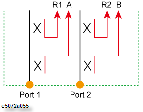
Absolute shows the absolute power for reference and received signals on the port.
|
Softkey |
Description |
|
A (n) |
Absolute measurement at Port 1, test receiver |
|
B (n) |
Absolute measurement at Port 2, test receiver |
|
R1 (n) |
Absolute measurement at Port 1, reference receiver |
|
R2 (n) |
Absolute measurement at Port 2, reference receiver |
where n in the parentheses is the stimulus port number. For example, R1(1) refers to the reference level when the signal is output from the Port 1, and A(2) refers to the received signal level at Port 1 when the signal is output from Port 2.
The AUX Input Ports can be used to input DC signal for DC signal measurement. This is useful in cases where the DUT (Device Under Test) works on a DC supply and is required to measure the DC supply along with other measurements of the DUT using the E5072A.
Example of AUX Input Measurement
Select Aux Input 1 or Aux Input 2 (depending upon the Aux port used for connection) by pressing the Meas.
Select Range (1V or 10 V)
Select Sweep Port (1-4) .
Click Format > Real.
Perform the measurements.
Sweep Port specifies the signal output port. For example, if sweep port is set to 1, the AUX input signal is measured while Port 1 on the front panel outputs the RF signal.