Other topics about Frequency Offset Measurement
The frequency-offset function allows you to measure frequency-translating devices such as mixers.
|
Item |
Description |
|
Sets frequency-offset
|
|
|
Sets external signal source (source of LO signal)
|
|
|
Changes frequency data.
|
|
|
Implements mixer calibration |
|
|
Measures conversion loss of mixer
|
The frequency-offset function allows you to implement the measurements in which frequencies are different for each port, such as in mixer measurement. The frequency set for each port can be applied to the port even if it is for stimulus or receiver.
You can set the frequency-offset for each channel independently.
The frequencies set at Port-n (n: any port number) should be a multiplier (Mn), divisor (Dn) and offset (On) for the basic frequency setting shown in the following formula.
<Port (n) Frequency> = <Basic Frequency> × Mn / Dn + On
The basic frequency is a frequency range set by the Start and Stop keys in the STIMULUS block.
Follow the steps below to set the frequency at each port.
Press Channel Next/Channel Prev to activate the channel on which the frequency-offset is to be set.
Press Sweep Setup, then click Frequency Offset to display the Frequency Offset Menu.
Click Port n (n: any port number) to display Port n Menu.
Set the frequency for Port-n by using the following softkeys:
|
Softkey |
Function |
|
Multiplier |
Sets a multiplier for the basic frequency |
|
Divisor |
Sets a divisor for the basic frequency |
|
Offset |
Sets an offset frequency for the basic frequency |
|
Start |
Sets a start frequency of the sweep range for Port-n |
|
Stop |
Sets a stop frequency of the sweep range for Port-n |
You can use both the Multiplier/Divisor/Offset and Start/Stop to set the frequency for each port. The use of the Multiplier/Divisor/Offset key is recommended as a rule. In this way, the offset value is automatically retained even if you have changed the setting range of the basic frequency, since the correlation of the frequencies among ports is defined as a formula. Using Start/Stop will set M and O, which can be determined from the specified frequency and the normal frequency, while maintaining the preset D.
Follow the steps below to enable the frequency-offset function.
Press Channel Next/Channel Prev to activate the channel of which the frequency-offset is to be set.
Press Sweep Setup, then click Frequency Offset to display Frequency Offset Menu.
Click Frequency Offset to turn ONN the frequency-offset function.
Once the frequency-offset function is enabled, the frequencies set at each port are displayed for each measured trace in the lower part of the screen.
Keep in mind the following when you turn ON the frequency-offset function:
If Swept is selected for the Sweep Mode, it will be changed to Stepped.
The phase information of the measurement value becomes meaningless. Therefore, the view of Phase, Group Delay, Smith, Polar, Real, Imaginary, Expand Phase or Positive Phase specified with Format has no actual meaning. In addition, any other function in the Conversion menu of the Analysis that cannot be calculated without phase information, including the parameter conversion function, will not operate correctly.
Fixture Simulator and Time Domain (Transform, Gating) are turned OFF.
If the measured frequency exceeds the measurable range, an error occurs during the measurement.
The number of sweeps during measurement increases. For example, you can use two sweeps to measure the S-Parameters of a 2-port setup in a normal frequency sweep; however, four sweeps are needed when the frequency-offset function is turned ON. This holds true regardless of whether the ports have the same frequency setting.
The E5072A allows you to control the external signal source that is connected to USB/GPIB interface.
To control the external signal source from the E5072A, you must connect its USB port and the external signal source's GPIB connector via the USB/GPIB interface. Then on the E5072A, you must specify the GPIB address and the type of external signal source.
The settings of the USB/GPIB interface must be made in advance. See Setting the GPIB for more information.
To use an external signal source, we recommend that you connect the E5072A's internal reference signal output connector and the external signal source's external reference signal input connector with BNC cable. This ensures stable measurement because the external signal source is phase-locked on the E5072A's frequency reference signal.
Follow the steps below to set GPIB address of the external signal source.
Press System.
Click Misc Setup> GPIB Setup > Signal Generator Address> Address.
Type the GPIB address of the external signal source you want to use.
The E5072A can use the external signal sources shown below.
|
Type |
Model |
|
1 |
User-defined Commands |
|
2 |
8643A, 8644B, 8664A, 8665A/B |
|
3 |
8648A/B/C/D, ESG Series, PSG Series & MXG Series |
For type 1, the user-defined commands can be used to control the external signal source. Four commands can be defined: preset, turning ON RF output, setting frequency, and setting power. Definitions are required for frequency and power level settings.
The factory-state definitions are shown below.
|
Function |
Command |
Description |
|
Preset |
"" |
Not defined |
|
Turning on RF output |
"R3" |
|
|
Frequency setting |
"FR %f% HZ" |
Frequency (Hz) is set to %f% |
|
Power level setting |
"AP %p% DM" |
Power level (dBm) is set to %p% |
Follow the steps below to select an external signal source.
Press System.
Click Misc Setup > GPIB Setup > Signal Generator Address.
Select the external signal source you want to use.
Switching Time allows you to set the wait time after setting the external signal source's frequency and power in ms.
The frequencies set to the external signal source should be a multiplier (MLO), divisor (DLO), and offset (OLO) for the basic frequency setting as shown in the following formula:
<LO Frequency> = <Basic Frequency> × MLO / DLO + OLO
The basic frequency is a frequency range set by the Start and Stop keys in the STIMULUS block.
Follow the steps below to set the external signal source frequency.
Press Sweep Setup, then click Frequency Offset to display the Frequency Offset Menu.
Click External Source > Power.
Set a frequency for the external signal source by using the softkeys.
You can use both the Multiplier/Divisor/Offset and the Start/Stop to set the external signal source frequency. The use of the Multiplier/Divisor/Offset key is recommended as a rule. This allows you to automatically retain the offset value even if you have changed the setting range of the basic frequency, since the external signal source frequency is defined as a formula. Using the Start/Stop key will set M and O, which can be determined from the specified frequency and the normal frequency, while maintaining the preset D.
Follow the steps below to set the external signal source power level.
Press Sweep Setup, then click Frequency Offset to display the Frequency Offset Menu.
Click External Source > Power and set the power level.
The mixer's conversion loss and reflection coefficients are significantly affected by the power level variation of the external signal source (LO signal). The Slope provided in the External Source Menu allows you to set a correction in dB/GHz for the power level variation that may occur when you change the external signal source frequency.
Follow the steps below to control an external signal source.
Press Sweep Setup, then click Frequency Offset to display the Frequency Offset Menu.
Click External Source to display the External Source Menu.
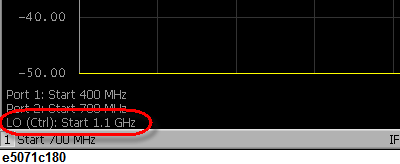
Click LO Frequency to turn it ON. The frequency setting of the external signal source (LO) is displayed.
Click Control to turn the external signal source control ON, which allows you to send setting values such as frequency to the external signal source and start the control. If the external signal source control is turned ON, (Ctrl) is displayed on the screen as shown below.
If the external signal source control fails, the GPIB setting may be wrong. See Setting the GPIB.
The frequency-offset function offers the capability to change the frequency data of each trace to any desired frequency.
Press Channel Next/Channel Prev and Trace Next/Trace Prev to activate the trace for which you want to change the frequency.
Press Sweep Setup, then click Frequency Offset to display the Frequency Offset Menu.
Use the X-Axis key to set the frequency data.
The basic frequency is a frequency range set by the Start and Stop keys in the STIMULUS bloc.
If you change the frequency data, it affects all of the measurement values, such as the marker's read value, conversion parameter, and conversion into time domain.
The E5072 provides a vector-mixer calibration function and a scalar calibration function for measuring frequency conversion devices.
For detailed information on mixer calibration, see Vector-Mixer Calibration and Scalar-Mixer Calibration.
Conversion loss is a typical measurement parameter of a mixer. As shown below, conversion loss indicates the level of efficiency in which input frequency is converted to another frequency. Furthermore, conversion loss can be defined as a proportion of output frequency power to input frequency power at a given LO signal level. The following description is based on an example of conversion loss measurement by using the vector-mixer calibration.
You must implement vector-mixer calibration in advance. For detailed information on vector-mixer calibration, see Vector-Mixer Calibration.
Connect the calibration mixer with the IF filter, measured mixer and external signal source, as shown below.
If two or more spectrum components are involved at a similar level, it is necessary to use a filter in order to prevent unnecessary spectrum components from entering the receiver port; in this way, you can prevent the total magnitude from reaching a damage level of 6.3 Vp-p.
Follow the steps below to set the measurement parameters. In this case, we measure each parameter of magnitude, phase, and group delay in conversion loss (S12).
Press Channel Next/Channel Prev to activate the channel you want to measure.
Press Display to set Num of Traces to 3.
Click Allocate Traces to select the Graph Layout (![]() ).
).
Press Meas to set the measurement parameter to S12.
Press Format to set LogMag (magnitude) to Trace 1.
Press Trace Next to select Trace 2.
Press Meas to set the measurement parameter to S12.
Press Format to set Phase (phase) to Trace 2.
Press Trace Next to select Trace 3.
Press Meas to set the measurement parameter to S12.
Press Format to set Group Delay (group delay) to Trace 3.
Press Scale to use Auto Scale All for trace scale optimization.
Change the frequency data to the desired frequency as required. For detailed information on changing the frequency data, see Procedures for changing frequency data.
For additional information about the absolute measurements, see Keysight application note 1463-6 Accurate Mixer Measurements Using the Frequency-Offset Mode, 5989-1420EN (Internet Connection is required to open).