Other topics about General Principles of Operation
A network analyzer supplies a sweep signal to a DUT, measures its transmission and reflection, and displays the results as ratios against the input signal from the signal source. The E5072A network analyzer consists of the circuit modules shown in the following figure.
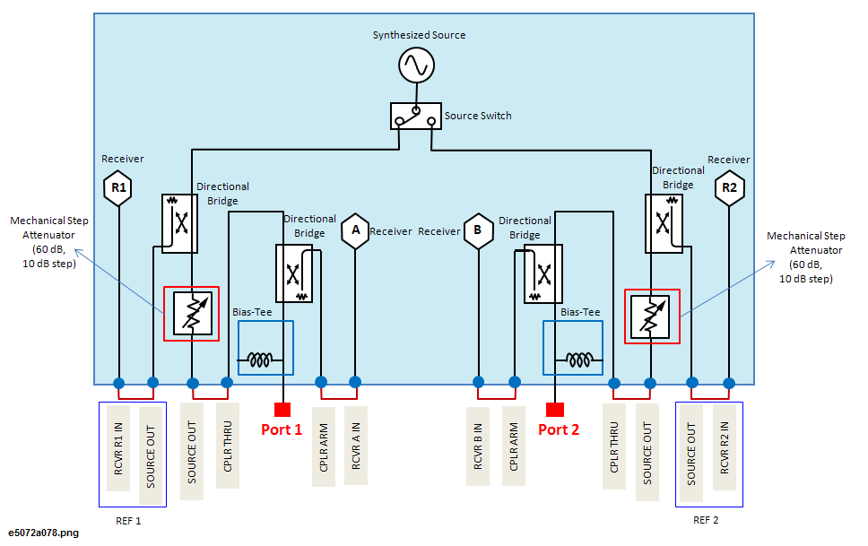
System Diagram for the E5072A Network Analyzer
The synthesized source generates an RF sweep signal in the specified frequency range.
The signal source is phase-locked to a highly reliable quartz crystal oscillator to maintain a high level of accuracy in its frequency as well as to achieve precise phase measurements. The level of RF output power is controlled with a power sweep range of 65dB. The maximum power level from ports is limited according to the frequency. See the Specifications.
The source switch is used to switch test ports to which the RF signal is supplied from the source.
The directional bridge detects input and output signals at the test ports. When the source switch is in port 1 side, the output signal and the reflection from the DUT are detected as the reference signal (R1) and the test signal (A), respectively. On the port 2, the signal that is transmitted through the DUT is detected as the test signal (B). All signals are then sent to the receiver.
There are two mechanical step attenuators, one for each port. Each mechanical step attenuator can be set independent of channel. The range of each mechanical step attenuator is 60dB with 10dB step. See Setting Stimulus Conditions for more information.
Each signal that is sent to the receiver is first converted into an IF signal by a mixer and then converted into a digital signal by an ADC (analog to digital converter). These processes are applied to each signal independently. The digital data is then analyzed by a micro processor and measurement results will be displayed on the screen.