CalPod is a system that simplifies the process of recalibrating the VNA without requiring the removal of the DUT or the physical connection of standards. This allows recalibration from a remote location such as when the DUT is in a temperature chamber.
Note: This feature is available to GCA and standard (S-Parameter) channels.
In this topic:
Note: The following overview assumes the CalPod system has been installed and configured. See the CalPod User's Guide for installation instructions at: http://na.support.keysight.com/pna/calpod/calpod_ug_85523-90005.pdf.
The following process assumes a 2-port DUT connected to the VNA ports 1 and 2 through CalPod modules as follows:
The Blue boxes represent CalPod modules with internal Thru, Short, Open, and Load states.
After configuring and assigning CalPod modules to VNA ports 1 and 2, connect the CalPod modules to the VNA, directly or using short cables. Learn how to configure CalPod.
Setup measurements on a channel. An IFBW of 1 kHz or lower with eight averages is recommended. CalPod does not support measurements below 100 MHz.
Perform a full 2-port calibration for the channel with the CalPod outputs as the reference plane.
Click Initialize Channel to automatically perform the following steps:
The OPEN, SHORT, AND LOAD states of both Calpod modules are switched in and S11/S22 are measured.
The resulting measurements are stored in the channel's Cal Set as additional standard measurements. These measurements are used to characterize the Calpod states - they are NOT used at this time to change the error correction.
|
Notes:
|
Connect the DUT to the CalPod outputs.
Click Recorrect Channel or Recorrect All Channels whenever necessary. Any of the following actions will cause the current calibration to become invalid and require recorrection:
Moving the CalPod modules to the ends of long cables.
Changing the cables.
Extreme temperature variations.
Measurement drift over long time periods.
The following steps occur automatically during recorrection for the active channel:
The OPEN, SHORT, AND LOAD states of both CalPod modules are switched in and S11/S22 are measured.
Additional (de-embedded) error terms are computed to compensate for changed conditions from the Initialize measurements.
Another Cal Set is created using the original name with the CalPod number appended. The modified error terms are saved to that Cal Set and applied to the channel. The measurements are now fully corrected.
How to start the CalPod dialog |
|
Using Hardkey/SoftTab/Softkey |
|
|
|
|
Learn all about the CalPod process.(Scroll up)
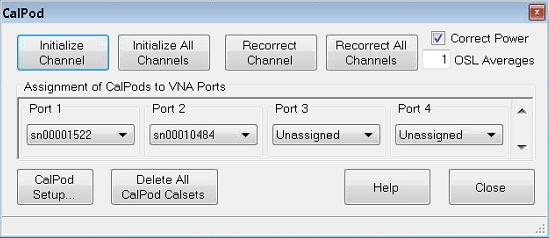
Initialize Channel Calibrated measurements of the CalPod states are performed as initial reference data points for the active channel. Initialize All Channels Calibrated measurements of the CalPod states are performed as initial reference data points for all current channels. This command is not recommended, it is generally preferable to initialize each channel immediately following calibration. Recorrect Channel Recorrects the active channel Cal Set to match the initial reference. Recorrect All Channels Recorrects the Cal Sets on ALL channels that were initialized. Correct Power This checkbox causes power to be recorrected ONLY when source power correction data is stored as error terms in the CalSet. This occurs only when a Guided Power Cal is performed and when an app channel is calibrated such as a FCA, GCA, IMD, and Noise Figure channel. This checkbox has NO effect when a S-parameter Cal or a standard Source Power Cal has been performed, because source power correction data is not stored in the CalSet. When any of the above power cals have been performed, and when this box is checked, the power output at the VNA port is adjusted to compensate for any change in path loss when Recorrect is performed. For example, if the path loss between the VNA port and the CalPod was increased by two dB following initialization, then the VNA output power will be increased by two dB upon recorrection. Do this when you add a significant amount of loss in the calibration path, or when the power level at the DUT is important. When a significant amount of loss is introduced in the calibration path, it may not be possible to increase the source power enough to overcome the loss. In this case, an Unleveled source message may appear on the VNA screen. When the checkbox is cleared, the source power level is not corrected. OSL Averages Controls the number of sweeps worth of raw measurements to be measured and averaged together for the recorrection computations for each state of each CalPod. Assignment of CalPods to VNA PortsFor each VNA port, select a CalPod module. CalPod Setup Starts the CalPod Setup dialog Delete All CalPod Cal Sets Deletes all recorrection Cal Sets and reinstates the Initialization Cal Set.
|
|
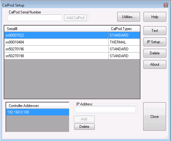
To start this dialog, click CalPod Setup in the CalPod dialog box. CalPod Serial Number Type the CalPod module (without 'sn'), then click Add CalPod. The new module is added to the list of available CalPod modules. Serial # and CalPod Types Shows the list of available CalPod modules. A CalPod module type may be STANDARD or THERMAL (include temperature correction). A CalPod module will be listed as a STANDARD type unless the thermal characterization data was previously loaded into the PNA from the USB flash drive that came with the CalPod. Once thermal characterization data has been loaded into the PNA, the CalPod is automatically listed in the CalPod Setup dialog. Note: Loading thermal characterization data from the USB flash drive is the only method of setting up a THERMAL CalPod. Simply entering the serial number in the CalPod Setup dialog will set the CalPod Type to be STANDARD. STANDARD and THERMAL data files are stored in C:\e-trak\adapters. ButtonsUtilities Launches the VNA CalPod Utilities used to configure the CalPod Controller and VNA over LAN. Note: Before using a CalPod Controller, the LAN MUST be set up using the CalPod Utilities or an error message will be displayed indicating that the VNA is unable to communicate with the CalPod Controller. Test Click to test the connection between the controller and the selected CalPod module. The message box displays the connection status and temperature for both Ambient and Thermal modules. Only the Thermal module will apply test temperature for recorrection. IP Setup Starts the IPSetup dialog box to confirm the CalPod controller settings. Delete Removes the selected STANDARD CalPod module from the list. To delete a THERMAL CalPod from the list:
About Shows the CalPod software version information. Controller Addresses Each controller can support 4 modules directly, and up to 48 modules using external splitters. Additional controllers may be required if more than 48 CalPod modules are needed. IP Address Enter the IP Address of the Controller, then click Add. The IP address is configured using the IPSetup Utility. The default IP=192.168.0.100, but different static network settings can be configured if required. Delete Select the Controller Address, then click Delete to remove the address from the list.
For more CalPod Setup information, see the CalPod web site: http://na.support.keysight.com/pna/calpod. Click CalPod Controller Configuration. |
This program is provided as a convenience to help determine the operational status of each 855xxA Series CalPod and its associated CalPod Controller. While this check is not intended to be a complete test, it does check each unit enough to provide greater than 95% confidence that the CalPod is functioning properly.
When the max frequency of the CalPod is higher than the max frequency of the VNA, the full frequency range of the CalPod is not tested.
Up to four CalPod modules may be checked at once. All four devices must be of the same frequency range.
The software revision for the Operator’s Check code is displayed in the upper left-hand corner of the window
The CalPod system must be installed and configured on the VNA.
See the CalPod User's Guide for instructions at: http://na.support.keysight.com/pna/calpod/calpod_ug_85523-90005.pdf
Required equipment:
An appropriate ECal or mechanical Cal Kit.
A high-quality cable.
A female-female adapter of the calibration connector type.
A fixed attenuator up to 10 dB (3 dB preferred) or other frequency insensitive device with similar loss.
Click Utility, then System, then Service, then Verification, then Operator's Check.
Click Setup Info to learn more about this dialog.
Also, click Cal Method or Connector for additional explanation for these areas.
Enter information in the “Configure” area.
Each time a 2-port cal is performed, the results are saved in a file. The “Use Prior” selection uses the saved calibration.
When the calibration connector type does not mate with the CalPod connectors, perform the calibration and then use adapters to connect to the CalPod module.
Click Begin to start the Op Check.
Follow the prompts in the gray box.
The Results area shows Op Check progress.
Click a test label for test information.
When the check has finished, the results are saved to a text file. The default path and filename is: C:/Program Files/Keysight/Network Analyzer/Service/calpodopchklog.txt. To save multiple results, rename the file or save it to a different location.
For assistance in troubleshooting CalPod Operator's Check failures or for additional information, see the appropriate FAQ at the CalPod web site: http://na.support.keysight.com/pna/calpod