Fixture Simulator


The following features allow you to mathematically add (embed) or remove (de-embed) circuits to, or from, your measurements. The mathematical models are applied to specific ports for all measurements on the channel.

Notes

See Also

Order of Fixture Operations

Click to learn more about each operation.

First, the following Single-ended measurement functions are processed in this order:

  1. Port Extensions

  2. 2-Port De-embedding

  3. Ground loop de-embedding / embedding

  4. Port Matching Circuit Embedding

  5. Port Z (Impedance) Conversion

  6. 4-Port Network (single-ended) Embed/De-embed

Then, Balanced measurement functions are processed in this order:

  1. Balanced Conversion

  2. Differential / Common Mode Port Z Conversion

  3. Differential Port Matching

Notes

How to select Fixturing Simulator

About Fixturing ON/off

BOTH of the following must occur to turn a fixturing selection ON.

EITHER ONE will turn a fixturing selection OFF.

  1. Turn Apply Fixtures ON/off
    Port Extensions is NOT affected by Fixturing ON/off.

  2. Check Enable on the individual fixturing selection dialog box.

Using Hardkey/SoftTab/Softkey

  1. Press Cal > Fixtures > Apply Fixtures.


Port Matching dialog box help

Note: This feature is available in the following measurement classes: GCA, Noise Figure, ,and standard (S-Parameter) channels.

This function specifies a circuit to embed (add) to the measurement results.  See Order of Fixture Operations.

Enable Port Matching  Check to apply the settings to the measurement results. Must also enable Fixturing ON/off.

Port - Select Port in which to apply simulation.

Circuit Model for Matching - Choose one of the following that best emulates your fixture at the selected VNA port:

Series L - Shunt C

VNA

DUT

Shunt C - Series L

VNA


DUT

Shunt L - Series C

VNA


DUT

Series C - Shunt L

VNA


DUT

Shunt L - Shunt C

VNA


DUT

User Defined (S2P File)

Load a file that is specified with User S2P File button.

None

Use no circuit model.

User S2P File  Click to specify an S2P file of the circuit model to embed at the selected port. If the normalized impedance value in a recalled User .S2P file is different from the port reference impedance setting of the VNA, the VNA setting is used.  

Circuit Values

Capacitance (C), Inductance(L), Resistance(R), Conductance(G)  Values for the specific components of the circuit type that models your fixture.

Reset  Restores the default values.


2 Port De-embedding dialog box help

Note: This feature is available in the following measurement classes: GCA, Noise Figure, ,and standard (S-Parameter) channels.

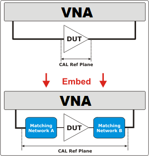
De-Embed when you have performed a calibration and then added a fixture (an adapter, an attenuator, a longer cable, etc.) that connects between the Cal reference plane and your DUT.  This function removes the effects of a component or test fixture from the measurement results.

Note: De-embedding a component with more than 20 dB of loss becomes impractical because of an inability to accurately measure the match of the DUT through such a device.

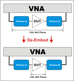
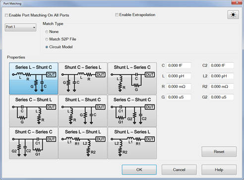
The de-embedding operation recalls an .s2p file (Touchstone format) which includes the electrical characteristics of a 2-port fixture or device. The file can be in any standard format (real-imaginary, magnitude-angle, dB-angle).

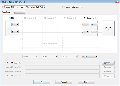
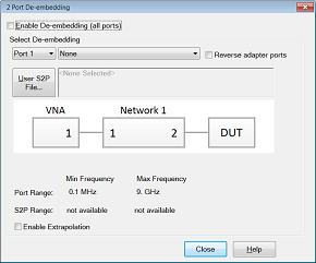
Enable De-embedding  Check to apply the settings to the measurement results. Must also enable Fixturing ON/off.

Enable Extrapolation  Check to apply a simple extrapolation when the S2P file has a narrower frequency range than the channel. The values for the first and last data points are extended in either direction to cover the frequency range of the measurement. The frequency ranges of both the channel and the S2P file are displayed at the bottom of the dialog.

When extrapolation is necessary and enabled, a message is displayed showing the frequency range to be extrapolated. When extrapolation is necessary and disabled, a message is displayed offering to enable extrapolation.

This setting also causes 4-port Extrapolation to be enabled and disabled.

Port  The VNA port to which the recalled de-embedding file is applied.

From the drop-down menu, select User Defined (S2P File).

Reverse Adaptor Ports  Check to cause the Fixture/Adapter to be configured with Port 2 connected to the VNA and Port 1 to be connected to the DUT. The image in the dialog reflects that change.

User S2P File  Click to specify an existing .S2P file. If the normalized impedance value in a recalled User .S2P file is different from the port reference impedance setting of the VNA, the VNA setting is used.  


Port Z (Impedance) Conversion dialog box help

Note: This feature is available in the following measurement classes: GCA, Noise Figure, ,and standard (S-Parameter) channels.

This function corrects the measurement and displays the results as if the measurement had been made into the specified impedance value. However, the physical port termination is still approximately 50 ohms.

The specified impedance value is applied to all of the measurements on ONLY the active channel.

See Order of Fixture Operations.

Enable Port Z Conversion  Check to apply the settings to the measurement results. Must also enable Fixturing ON/off.

R  Real part of the impedance value.

jX  Imaginary part of the impedance value.

Close  Applies the entries and closes the dialog box

Note:  Port Z (Impedance) conversion uses values in the following prioritized order:

  1. Balanced (Differential or Common Mode) - if enabled, these values are always used.

  2. Single Port Impedance - if enabled, this value is used if Balanced is not enabled.

  3. System Impedance - if neither balanced or single port is enabled, this value is used.


4/6/8-Port Embed/De-embed dialog box help

This function specifies a single-ended 4-port circuit (*.S4P file) to embed (add) or de-embed (remove) from the measurement results. Computation takes place BEFORE Balanced conversion. See Order of Fixture Operations.

There is a single normalized impedance value for each port in the *.S4P file. This impedance value must match the impedance of the previous Port Z setting, or the VNA port impedance.

The VNA will interpolate if the number of data points that are read is different from the current VNA setting.

Enable 4-Port Embed/De-embed  Check to apply the settings to the measurement results. Must also enable Fixturing ON/off.

Enable Extrapolation  Check to apply a simple extrapolation when the S4P file has a narrower frequency range than the channel. The values for the first and last data points are extended in either direction to cover the frequency range of the measurement. The frequency ranges of both the channel and the S4P file are displayed at the bottom of the dialog.

When extrapolation is necessary and enabled, a message is displayed showing the frequency range to be extrapolated. When extrapolation is necessary and disabled, a message is displayed offering to enable extrapolation.

This setting also causes 2-port Extrapolation to be enabled and disabled.

Topology

Select a DUT topology. Refer to the images on the 4-port embed/De-embed dialog box.

  • A - Network 1

  • B - Network 1/3

  • C - Network 1/2/4

NA Ports - Select the VNA Port that is connected to each circuit port.

Network Ports Select the network ports that represent the configuration of the S4P file.  By default, ports 1 and 2 are connected to the VNA and ports 3 and 4 are connected to the DUT.

None, Embed, De-embed  For Network1 and Network2, select:

Browse  For both Network1 and Network2, navigate to find the .*S4P file to embed or de-embed.

OK  Applies the changes and closes the dialog box.

Cancel  Does NOT apply the changes and closes the dialog box.


Differential Impedance Conversion dialog box help

This function sets the Differential impedance value for each balanced port.

The default value for R: is the SUM of the impedance values for both ports that make the logical port. If Port Z Conversion is not enabled, then System Z0 values for both ports are summed.

See Order of Fixture Operations.

Enable Differential Z Conversion  Check to apply the settings to the measurement results. Must also enable Fixturing ON/off.

Logical Port  Select the logical (balanced) port to receive impedance value. To see logical port numbers, see the measurement topology.

R  Real part of the impedance value.

jX  Imaginary part of the impedance value.

Close  Closes the dialog box.

See note about Port Impedance priority.


Common Mode Impedance Conversion dialog box help

This function sets Common Mode Impedance value for each balanced port.

The default value for R: is calculated as follows.

(Z1 * Z2) / (Z1 + Z2)

Where ports 1 and 2 comprise the logical port:

Z1 = the Port Impedance values for port 1

Z2 = the Port Impedance values for port 2

If Port Z Conversion is not enabled, then System Z0 values for port 1 and 2 are used in the calculation.

See Order of Fixture Operations.

Enable Common Mode Z Conversion  Check to apply the settings to the measurement results. Must also enable Fixturing ON/off.

Logical Port  Select the logical (balanced) port to receive impedance value. To see logical port numbers, see the measurement topology.

R  Real part of the impedance value.

jX  Imaginary part of the impedance value.

Close  Closes the dialog box.

See note about Port Impedance priority.


Differential Port Matching dialog box help

This function allows the embedding of a differential matching circuit at a balanced port.

See Order of Fixture Operations.

Enable Differential Port Matching   Check to embed the selected matching circuit to the measurement results. Must also enable Fixturing ON/off.

Logical Port  Choose Logical DUT port to receive the selected matching circuit. To see logical port numbers, see the measurement topology.

Select Circuit  Select a matching circuit. Choose from:

  • Shunt L - Shunt C  Predefined circuit.

Circuit Values  Choose from:

    • C  Capacitance value

    • G  Conductance value

    • L  Inductance value

    • R  Resistance value

  • User defined  Select an *.S2P file that represents the matching circuit. Then click Browse to navigate to the *.S2P file.

Note: For the *.S2P file:
Port 1 of the circuit is assumed to be connected to the VNA
Port 2 of the circuit is assumed to be connected to the DUT.

  • None  No embedded circuit on selected port.

Close  Closes the dialog box.


Power Compensation dialog help

Note: This feature is available in ALL measurement classes.

This function adjusts the source power at the specified port to compensate for the combined amount of gain or loss through specific fixturing operations. Use this function to set the power level at the DUT input.

Power Compensation adjusts the source power for the gain/loss through 2-port de-embedded fixture components.

  • It does not compensate for any port matching networks.

    • To work around this limitation, compute the anti-network of the matching circuit and use that data to generate an S2P file.  Change the fixture type from port matching to De-embed.  This should result in the same measurement data but will also enable the port power compensation feature.

  • It does not compensate for any fixture networks with more than 2 ports.

    • There is no work around for this limitation.  There is a coarse adjustment for port power using Power Offsets.  Calculate the loss through the fixture, use that number to set the power offset, and then set the desired power level at the port.

For example:

  • Your DUT requires a fixture on the input port which is connected to VNA port 1.

  • The fixture description (such as an S2P file at the 2-port De-embed function) indicates the fixture has approximately 2 dB of loss across the frequency span.

  • You set source power to 0 dBm. But you want 0 dBm at the DUT input (the fixture output).

  • Check Power Compensation on Port 1 and enable Fixturing.

  • Power Compensation causes the source power to be increased by approximately 2 dB so that the power at the fixture output plane will remain at 0 dBm.

Power Compensation affects all measurements in the channel.

Enable Fixturing to use Power Compensation.

Note: Use caution when applying power compensation.  Always test your setup without a DUT in a place. If you are using S2P files, Recall your S2P file into the VNA so you can verify that the device your S2P file describes is what you intended it to be. It is  too easy to misalign data in S2P files if they are constructed by hand.

Ground Loop De-embedding / Embedding

Ground loop de-embedding removes the effect of a non-ideal ground connection between the DUT’s ground and the analyzer's ground reference. Typically, the non-ideal component is the parasitic inductance of the ground contacts.

Ground loop embedding adds the effect of a non-ideal component on the ground contacts.

The Ground Loop De-embedding / Embedding can be specified by circuit model type or touchstone file.

Ground loop de-embedding / embedding is only available from SCPI remote interface.

Fixture Simulator Example

The following example shows a DUT and the matching circuit with which the DUT will be used in its intended application. When the DUT is tested in a high-volume manufacturing environment, multiple test fixtures are often required. The most accurate way to test the DUT and ensure measurement consistency between the different test fixtures is to use a simple, repeatable, test fixture without the actual matching elements.

To get the desired performance data, the parasitic effects of the fixture must first be removed (de-embedded) from the measured data. Then a perfect "virtual" matching circuit must be simulated and added mathematically (embedded) to the corrected, measured data. The result is an accurate display of the DUT as though it was actually tested with a physical matching circuit, but without the uncertainties of using real components.

Test Device and the circuit in which it will be used.


Circuit Simulation

This diagram does NOT refer to the order in which operations are performed.

See Order of Fixture Operations.

  1. Create a balanced measurement using single-ended to balanced (SE-Bal) topology. Include all relevant measurement settings (IFBW, number of points, and so forth). Once the measurement is created and calibrated, the measurement parameter can be easily changed. For example, Sdd22 to Sds21.

  2. Calibrate the measurement at the point where the simple test fixture is connected to the VNA. Use accurate calibration standards and definitions.

  3. Remove the effects of the three uncalibrated transmission lines of the simple test fixture. This can be done in several different methods. The easiest is to use manual or automatic Port Extensions to move the calibration reference plane to the DUT. This removes the electrical length and loss of the fixture’s transmission lines, but does not account for fixture mismatch. Another method is to de-embed previously-created *.S2p files of the 3 transmission lines. The files can be created using external ADS modeling software. Another alternative is to create the *.S2P files by independently measuring all 3 ports of the test fixture and saving the results of each to an S2P file.

  4. With the test fixture connected to the VNA and a DUT inserted, the measurement results now appear as though calibration was performed at the connections to the DUT, and the device was measured in a 50-ohm single-ended test environment. The following steps will cause the results to reflect the performance of the device as though the device is embedded in the circuit in which it will be used.

  5. Port 1 of the device is a single-ended port and sees a source impedance the same as the VNA system impedance, so no change is required. However, if Rs were a value other than 50 ohms, Port 1 Impedance Conversion would be used to simulate the different impedance.

  6. Port Matching is used to simulate L1 inductance. Select any of the Shunt L circuits to embed (add) to the measurement results. Enter the value of L and R. The C and G values can be entered as 0 (zero).

  7. Port Matching is used to simulate C1 and C2 capacitance. For both port 2 and port 3, select any of the Series C circuits to embed (add) to the measurement results. Enter the value of C and G. The L and R values can be entered as 0 (zero).

  8. Balanced Conversion mathematically simulates the measurement in balanced mode.

  9. Differential Port Matching is used to simulate L2 inductance. Select Shunt L- Shunt C and enter the inductance / resistance value. The C and G values can be entered as 0 (zero).

  10. Finally, Differential Z Conversion is used to simulate a circuit termination of 200 ohms. If you are making Common Mode measurements, specify Common Mode Z Conversion.