Last Updated: August 29, 2007
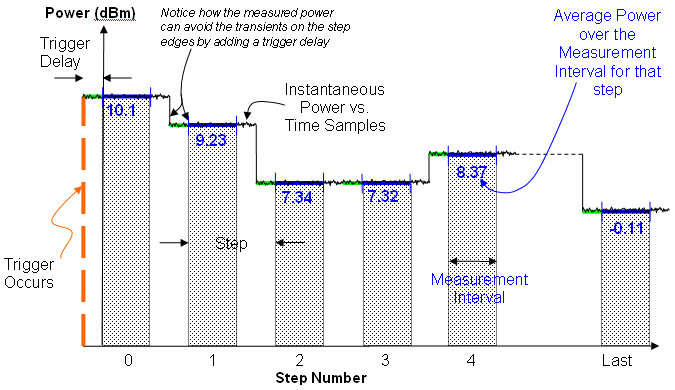
The Dynamic Power measurement provides a fast and flexible method for calibrating the power accuracy of a wireless device (which could have its power changing over time). Once the wireless device has provided a suitable trigger, the Dynamic Power measurement tracks and reports the power result for each step. The step length and the number of steps are defined by you. This power is integrated in time over the specified measurement interval in each step. By setting the measurement interval shorter than the step length and adjusting the trigger delay, you can avoid the transients caused by the power step. A number of power measurement bandwidths are available, which provide support for many different radio standards. A conceptual graphic of the Dynamic Power is shown in the following graphic.
You must set the expected power of the test set's RF Analyzer to the maximum power of the wireless device expected in the sequence. If the actual maximum power is greater than 2 dB from the expected power, the test set's RF analyzer may be over-driven. If the wireless device has large power errors, it is recommended that you first measure the maximum power step with the Channel Power measurement that is part of the RF Channel Measurement Suite, and then set the expected power to the appropriate level.
Typically the dynamic range of this measurement is 45 dB therefore if the signal-to-noise ratio is unacceptable at lower power levels, you may need to run the measurement again using a new lower RF analyzer expected power level.
There are several parameter couplings for this measurement which are described below:
The Step
Length, Number of Steps, and Measurement
Interval parameters are all coupled to the setting of the Filter parameter.
For each filter the settings of these parameters are unique. Therefore,
changing the setting of the filter results in these other parameters being
updated to a new set of corresponding values.
It is recommended that you change these parameters in the following
order:
Filter
Step Length
Measurement Interval
Number of Steps
On the remote interface, for each filter you can set each of these coupled parameters.
|
Filter |
Step Length |
Measurement Interval |
Number of Steps |
|
1 kHz |
0.5 to 180 ms |
0.5 ms to Step Length |
1 to (1048000 / (21973 x Step Length)) |
|
30 kHz |
0.25 to 180 ms |
0.25 ms to Step Length |
1 to (1048000 / (60e3 x Step Length)) |
|
100 kHz |
0.1 to 20 ms |
0.25 ms to Step Length |
1 to (1048000 / (250e3 x Step Length)) |
|
300 kHz |
0.1 to 20 ms |
0.1 ms to Step Length |
1 to (1048000 / (600e3 x Step Length)) |
|
640 kHz |
0.1 to 20 ms |
0.1 ms to Step Length |
1 to (1048000 / (1.28e6 x Step Length)) |
|
1.23 MHz |
0.1 to 20 ms |
0.1 ms to Step Length |
1 to (1048000 / (2.46e6 x Step Length)) |
|
1.28 MHz |
0.1 to 20 ms |
0.1 ms to Step Length |
1 to (1048000 / (2.56e6 x Step Length)) |
|
1.6 MHz |
0.1 to 20 ms |
0.1 ms to Step Length |
1 to (1048000 / (3.2e6 x Step Length)) |
|
3.84 MHz |
0.1 to 20 ms |
0.1 ms to Step Length |
0.1 to (1048000 / (7.68e6 x Step Length)) |
|
5 MHz |
0.1 to 20 ms |
0.1 ms to Step Length |
0.1 to (1048000 / (10e6 x Step Length)) |
|
EGPRS 8PSK ECP |
0.575 to 20 ms |
542.8 μs |
1 to 1047800 / (1.0833e6 x Step Length) |
|
GSM Tx power |
0.1 to 20 ms |
0.1 ms to Step Length |
1 to (1048000 / (320e3 x Step Length)) |
|
W-CDMA mean power |
0.1 to 20 ms |
0.1 ms to Step Length |
1 to (1048000 / (5.25e6 x Step Length)) |
Number
of Steps and Measurement Interval are coupled
to the Step Length.
If the Step Length changes, then Number
of Steps and Measurement Interval are coupled
but only for range validation.
This parameter sets the type of filter for Dynamic Power measurements.
The GSM Tx power and W-CDMA mean power filters are both compliant with their respective standards. These filters are more efficient and therefore improve test time for their respective technologies. These filters also provide the maximum number of steps that can be made in the dynamic power measurement. It is recommended that you use the technology specific filters (GSM Tx power and W-CDMA mean power) except in certain situations where out-of-channel performance is of great importance. For example, you would not use the technology specific filters if there is a very large signal in an adjacent channel.
The GSM Tx power filter has the same noise bandwidth as the 300 kHz filter, however the sampling frequency is lower (320 kHz versus 600 KHz) so that dynamic power measurements with this filter provide the maximum number of steps.
The W-CDMA mean power filter is the same filter that is used in the W-CDMA Fast Device Tune measurement. This filter has approximately the same noise bandwidth (4.97 MHz) as the 5.0 MHz filter, however the sampling frequency is lower (5.25 MHz versus 10 MHz) so that dynamic power measurements with this filter provide the maximum number of steps.
Selecting EPSK ECP selects both a filter and causes the EGPRS 8PSK Estimated Carrier Power algorithm to be run. This takes out the data dependent effects on the power. This filter should only be selected if the signal is an EGPRS 8PSK signal with a valid midamble. When using this filter you must set the Expected Burst Type parameter to the correct value.
The 1.28 MHz filter is a Root-Rasied-Cosine (RRC) filter. It can be used for making TD-SCDMA RRC filtered mean power measurements.
The 1.6 MHz filter is a very sharp filter and is useful for making TD-SCDMA power measurements.
SCPI command: SETup:DPOWer:FILTer[?]
This parameter sets the step length for Dynamic Power measurements.
SCPI command: SETup:DPOWer:SLENgth[:SELected][?]
This parameter sets the measurement interval for Dynamic Power measurements.
SCPI command: SETup:DPOWer:INTerval[:SELected][?]
This parameter sets the number of steps for Dynamic Power measurements.
SCPI command: SETup:DPOWer:STEPs[:SELected][?]
This parameter applies an overlay of the individual power samples on to the graphical results. This can help you to identify synchronization issues between the wireless device and the test set. You may want to use this overlay during your test development to optimize your test set up.
SCPI Command: SETup:DPOWer:CPSamples:STATe[?]
This parameter sets the trigger state to single trigger mode or continuous trigger mode for Dynamic Power measurements.
SCPI command: SETup:DPOWer:CONTinuous[?]
This parameter sets the trigger source for Dynamic Power measurements.
SCPI command: SETup:DPOWer:TRIGger:SOURce[?]
This parameter sets the trigger delay in seconds for Dynamic Power measurements.
SCPI command: SETup:DPOWer:TRIGger:DELay[:SELected][?]
This parameter sets the trigger threshold for Dynamic Power measurements.
SCPI command: SETup:DPOWer:TRIGger:THReshold[?]
This parameter sets the timeout value in seconds for Dynamic Power measurements.
SCPI command: SETup:DPOWer:TIMeout[:STIMe][?]
This parameter sets the crest factor for the Dynamic Power, RF Channel, and Spectrum Monitor measurements. Changing the setting within this measurement setup automatically changes it for the other measurements. The crest factor allows the test set to range correctly and therefore helps prevent over-ranging. The higher the crest factor the less likely that an over-range will occur, however the dynamic range is decreased.
SCPI command: SETup:GPMeas:CFACtor[:SELected][?]
This parameter sets the expected burst type when the filter is set to EPSK ECP. This is the same parameter that is available on the RF Analyzer tab.
SCPI command: RFANalyzer:BURSt:TYPE[:SELected][?]
The Dynamic Power measurement provides graphic and numeric results.
This result provides the integrity indicator for the Dynamic Power measurement. Normal indicates that the measurement completed successfully without error and the result is accurate. For details of other integrity indicators, see Measurement Integrity Indicator.
SCPI command: FETCh:DPOWer:INTegrity?
This result provides the number of steps measured in the Dynamic Power measurement.
SCPI commands: FETCh:DPOWer:COUNt[:STEP]?, FETCh:DPOWer:SPOWer?
These results provide the Individual power levels for each step in dBm.
SCPI command: FETCh:DPOWer:SPOWer?
The graphical results are available on the Dynamic Power Graphic tab as shown below.
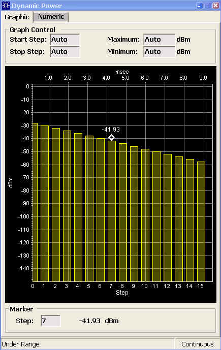
The Graphic tab has a number of parameters that allow you to control the graph and its marker position:
You can choose to set the graph parameters manually or automatically. To change between Auto and Manual, either right-click the parameter and chose Switch to Auto or Switch to Manual from the pop-up menu, or press the On/Off (Auto/Manual) key.
The Start Step and Stop Step parameters allow you to define which dynamic power step is displayed at the start and end of the graph respectively. If you set either of them to Auto the other automatically changes to Auto.
The Maximum and Minimum parameters allow you to define the upper and lower limits of the graph in dBm. If you set either of them to Auto the other automatically changes to Auto.
The Marker Step parameter allows you to enter a specific dynamic power step which the marker will locate to. The level of that specific step is then displayed in dBm.
The numeric results are available on the Dynamic Power Numeric tab as shown below.
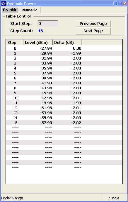
The Numeric tab has a number of parameters that allow you to control the table:
The Start Step parameter allows you to define the step that appears as the first entry in the list of results.
The Step Count displays the value set using the Number of Steps parameter in the Dynamic Power Setup window. If there are no measurement results available it displays "___".
The list of results displays a maximum of 25 results at one time. If you want to see results from other steps you can use the Previous Page and Next Page keys.
The Dynamic Power measurement does not perform autoranging.
The Dynamic Power measurement will complete and meet its measurement accuracy specifications when the signal meets the following input signal conditions:
Input signal level is between -60 dBm and +35 dBm.
Maximum signal power must be within +2 dB and -2 dB of the expected input level with ≤ 4 dB crest factor.
Triggering choices available for the Dynamic Power measurement are Immediate, Rise, Fall, and External.
Related Topic: Programming a Dynamic Power (DPOW) Measurement