Last Updated: August 29, 2007
This measurement is only applicable with a PAvT license.
The Phase and Amplitude versus Time measurement provides a way to characterize the magnitude and phase errors introduced by the non-linear effects of power amplifiers operating over a wide dynamic range. Measurements, such as amplitude, phase and frequency as a function of output level make it possible to create a more accurate output signal by pre-distorting the input signal to the power amplifier.
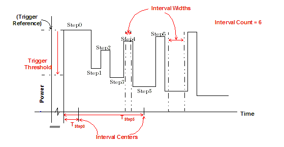
This measurement is performed on a signal that consists of a discrete amplitude step waveform (discrete waveform calibration signal). This measurement requires you to put your wireless device into a test mode that can command the wireless device to generate a discrete waveform.
The discrete waveform calibration signal may include up to 512 measurement steps, which can be of varying widths (100 μs to 512 ms) and amplitudes (-20 dBm to +35 dBm). All the steps in a discrete waveform must be at the same carrier frequency.
For the measurement to complete properly, the level of the initial step should be at the maximum power level setting of the waveform. The maximum power setting is used to range the measurement and can be used as the reference for the trigger level, which is set by configuring the Trigger Threshold parameter. The Trigger Delay should also be configured prior to measuring the waveform. A wait is needed after the measurement initiates and before the waveform's RF Rise trigger event occurs.
There are parameters specific to the discrete waveform that you should set prior to measuring the discrete waveform. These parameters are necessary to completely define where the test set makes measurements on the discrete waveform. Therefore each time you enter a new Step you must define it's Center and Width.
The total sampling time of the measurement is the largest Center plus half of the corresponding Width. The maximum sampling time is 512 ms. Therefore if the largest Center plus half of the corresponding Width exceeds 512 ms, the test set returns integrity indicator 21 (Parameter Error).
Before starting the measurement you should specify the wireless device's Frequency and the Expected Power on the test set's RF Analyzer. The Expected Power should be set to the maximum power level in the wireless device generated waveform, and the test set's RF Generator's Output Power should be set to Off.
This measurement can be armed as a single measurement only. Once triggered, the test set performs a measurement on the wireless device's generated waveform.
The test set returns amplitude, phase, and frequency results. The test set samples the discrete waveform at an effective rate of 156.25 kHz. For details on the measurement results see Phase and Amplitude versus Time Measurement Results.
The figure below is an example of a discrete waveform calibration signal.
The Center and Width values are entered into tables on the setup window. You can navigate the rows and columns of the table using the up, down, left and right arrow keys. The first column of the setup table is the Step and the other columns are for entering the Center and Width values. You can jump directly to any Step by entering the step number in the first column. Also, the softkeys allow you to do the following operations to the selected entries: Insert Entry Above, Insert Entry Below, or Remove Current Entry.
This parameter sets the level below the maximum power level at which the measurement triggers. That is, the trigger threshold is the offset below the Expected Power plus the Amplitude Offset value. This parameter only applies if the Trigger Source is set to Rise.
SCPI command: SETup:PAVTime:TRIGger:THReshold[?]
This parameter sets the trigger source for Phase and Amplitude versus Time measurements. You can set it to Rise or External. This parameter also accepts the Immediate trigger source setting, however it has no affect on this measurement.
SCPI command: SETup:PAVTime:TRIGger:SOURce[?]
This parameter sets the specified time between the trigger event and when the test set begins sampling data for Phase and Amplitude versus Time measurements.
SCPI command: SETup:PAVTime:TRIGger:DELay[?]
This parameter sets the timeout value in seconds for Phase and Amplitude versus Time measurements.
SCPI commands: SETup:PAVTime:TIMeout[:STIMe][?]
This parameter details the total number of steps the test set is to measure. To adjust the number of steps to be measured use the softkeys.
SCPI command: SETup:PAVTime:STEP:COUNt?
This parameter sets the time location of the center of each step relative to the time when the trigger event occurs.
SCPI command: SETup:PAVTime:STEP[:POINts][?]
This parameter sets the stable portion, or portion you wish to measure, of each power step.
SCPI command: SETup:PAVTime:STEP[:POINts][?]
The Phase and Amplitude versus Time measurement provides graphic and numeric results. The measurement completes without returning a 5 (Over Range) or 6 (Under Range) integrity indicator as long as the measured power is within ±6 dB of the expected power for that burst. However, measurement accuracy is warranted only if the measured power is within 3 dB of the expected power.
This result provides the integrity indicator for the Phase and Amplitude versus Time measurement. Normal indicates that the measurement completed successfully without error and the result is accurate. For details of other integrity indicators, see Measurement Integrity Indicator.
SCPI command: FETCh:PAVTime:INTegrity?
These results provide the amplitude of each measurement step. The result for the first measurement step is slightly different from the rest. The first measured power result is an absolute power measurement. All subsequent measurement results are relative to the results of the first measurement step.
SCPI command: FETCh:PAVTime:POWer?
These results provide the phase of each measurement step. The phase result for the first measurement is slightly different from the rest. The first phase result is set to 0°. All subsequent measurement results are relative to the results of the first measurement step.
SCPI command: FETCh:PAVTime:PHASe?
These results provide the frequency of each measurement step. The frequency result for the first measurement is slightly different from the rest. the first frequency result is the offset relative to the expected input frequency (which is set using the SCPI command RFANalyzer:MANual:FRequency:GCALibration). A negative frequency result indicates the first measurement step is below the expected input frequency, and a positive result indicates the first measurement step is above the expected input frequency. All subsequent measurement results are relative to the results of the first measurement step.
SCPI command: FETCh:PAVTime:FERRor?
Types of Signals Measured: CW
Frequency Capture Range: Signal must be within ±100 kHz of test sets expected frequency
Measurement Level Ranging: Manual. For specifications to be met, the maximum signal power must be within ±3 dB of the expected power, with a 0 dB crest factor.
Minimum Input Level: -40 dBm
Measurement Synchronization: Requires careful configuration of the measurement. An external controller needs to be used to control the wireless device and force it to generate the waveform. The measurement must be armed and ready before the wireless device starts to transmit.
Measurement Trigger Arm: Single
![]()