Keypad access
The Instrument Settings screen, accessed from either the keypad or the multi-touch display, provides the various instrument settings described in this topic.
Keypad access
 Multi-touch access
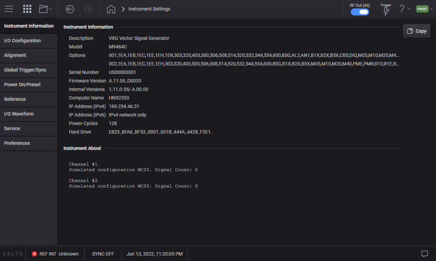
This tab brings up a display of instrument information, as shown below. The Copy button copies this information to the clipboard for pasting into Windows programs.
Some of this information is available via SCPI commands, as described in Internal Versions.
|
GUI Location |
System Menu > Settings (gear icon) > System Information |
|
Initial S/W Revision |
A.01.00 |
The instrument software contains a number of internal components. The Internal Versions displays versions of the primary internal components as determined by Keysight Technologies. The number of versions reported and the formatting may change on any given software release.
|
GUI Location |
System Menu > Settings (gear icon) > System Information > Internal Versions |
|
SCPI Command |
:DIAGnostic[:CPU]:INFormation:REVision? |
|
SCPI Example |
DIAG:INF:REV? |
|
Notes |
The return value is a string. The formatting and number of versions may change in any given software release. Thus, any program using this string should be implemented in a way that does not rely on the contents in a strict manner. |
|
Initial S/W Revision |
A.01.00 |
|
Modified S/W Revision |
A.04.00 |
Some of this information is available via SCPI commands as follows:
*IDN? - Identification Query provides Model number, Serial number, and Firmware version.
*OPT? - Query Instrument Options provides the comma separated options string.
Opens the I/O Configuration menu, which lets you display the VISA addresses, and configure GPIB, SCPI Services, and SCPI Options.
|
GUI Location |
System Menu > Settings (gear icon) > IO Configuration |
|
Initial S/W Revision |
A.01.00 |
|
Modified S/W Revision |
A.04.00 |
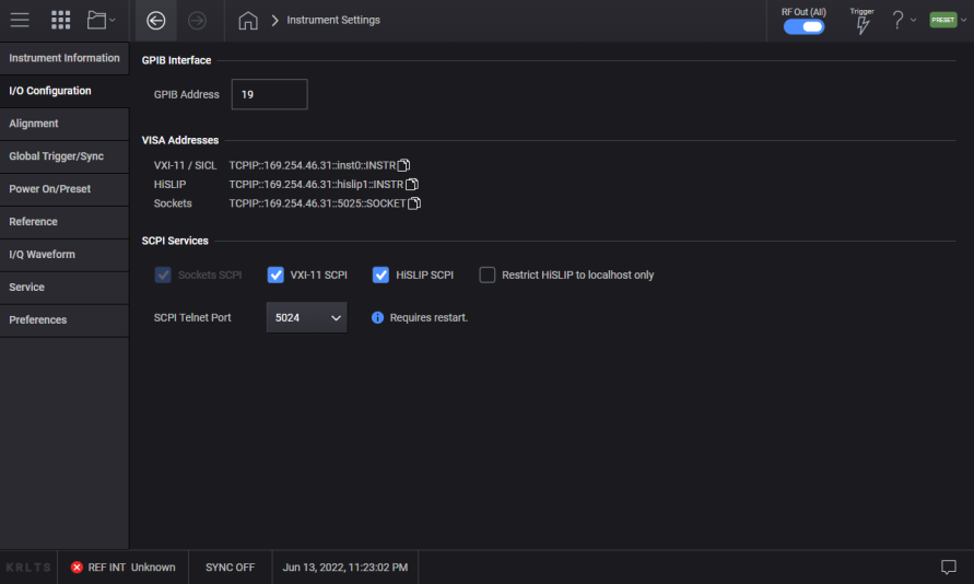
Specifies the GPIB address of your instrument.
|
GUI Location |
System Menu > Settings (gear icon) > I/O Configuration > GPIB Address |
|
SCPI Command |
:SYSTem:COMMunicate:GPIB:ADDRess <integer> :SYSTem:COMMunicate:GPIB:ADDRess? |
|
SCPI Example |
:SYST:COMM:GPIB:ADDR 19 |
|
Notes |
Changing the Address on the GPIB port requires all further communication to use the new address. |
|
Preset |
This is unaffected by Preset but is set to 19 on a “Restore System Settings to Default Values” |
|
State Saved |
No |
|
Range |
0 to 30 |
|
Initial S/W Revision |
A.01.00 |
Turns the FTP server in your instrument on and off.
|
SCPI Command |
:SYSTem:COMMunicate:SCPI:SOCKets ON|OFF|1|0 :SYSTem:COMMunicate:SCPI:SOCKets? |
|
SCPI Example |
:SYST:COMM:SCPI:SOCK ON |
|
Preset |
This is unaffected by Preset but is set to ON on a “Restore System Settings to Default Values” |
|
State Saved |
No |
|
Initial S/W Revision |
A.01.00 |
Turns the VXI-11 server in your instrument on and off.
|
GUI Location |
System Menu > Settings (gear icon) > I/O Configuration > VXI-11 SCPI |
|
SCPI Command |
:SYSTem:COMMunicate:SCPI:VXI11 ON|OFF|1|0 :SYSTem:COMMunicate:SCPI:VXI11? |
|
SCPI Example |
:SYST:COMM:SCPI:VXI11 |
|
Preset |
This is unaffected by Preset but is set to ON on a “Restore System Settings to Default Values” |
|
State Saved |
No |
|
Initial S/W Revision |
A.01.00 |
Turns HiSLIP in your instrument on and off.
|
GUI Location |
System Menu > Settings (gear icon) > I/O Configuration > HiSLIP SCPI |
|
SCPI Command |
:SYSTem:COMMunicate:SCPI:HISLip ON|OFF|1|0 :SYSTem:COMMunicate:SCPI:HISLip? |
|
SCPI Example |
:SYST:COMM:SCPI:HISL |
|
Preset |
This is unaffected by Preset but is set to ON on a “Restore System Settings to Default Values” |
|
State Saved |
No |
|
Initial S/W Revision |
A.01.00 |
The instrument provides basic SCPI I/O via a telnet port. The default port is 5024. The ability to change the port to 5023 is provided.
NOTE: changing the SCPI Telnet Port requires restarting the instrument application for the change to take effect.
|
GUI Location |
System Menu > Settings (gear icon) > I/O Configuration > SCPI Telnet Port |
|
SCPI Command |
:SYSTem:COMMunicate:LAN:SCPI:TELNet:PORT 5023|5024 :SYSTem:COMMunicate:LAN:SCPI:TELNet:PORT? |
|
SCPI Example |
:SYST:COMM:LAN:SCPI:TELN:PORT 5023 |
|
Preset |
Not reset by Preset, set to 5024 with Restore System Settings to Defaults. |
|
Initial S/W Revision |
A.04.00 |
Sets how the instrument should power on and activate certain presets.
|
GUI Location |
System Menu > Settings (gear icon) > Power On/Preset |
|
Initial S/W Revision |
A.01.00 |
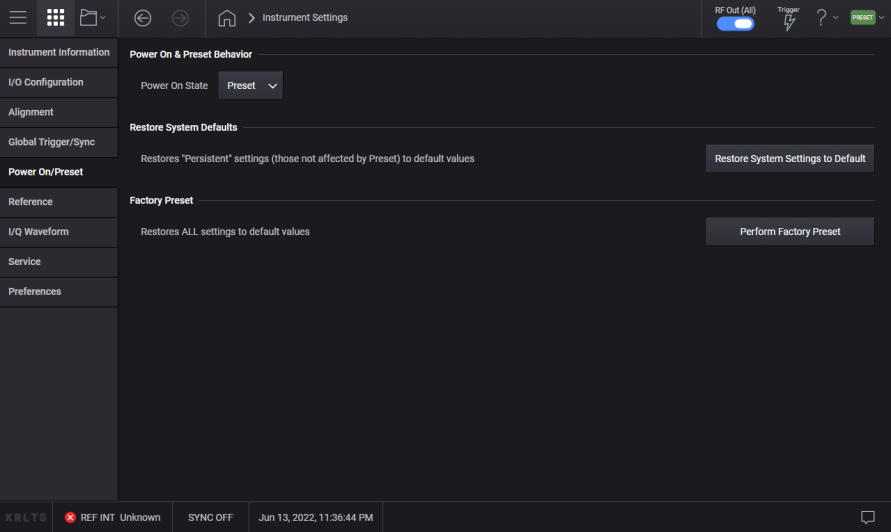
Selects whether the instrument powers up in a default state or some other state.
|
GUI Location |
System Menu > Settings (gear icon) > Power On/Preset > Power On State |
|
SCPI Command |
:SYSTem:PON:TYPE PRESet|USER|LAST :SYSTem:PON:TYPE? |
|
SCPI Example |
:SYST:PON:TYPE PRES :SYST:PON:TYPE USER :SYST:PON:TYPE LAST |
|
Preset |
This is unaffected by a Preset but is set to Preset on a “Restore System Settings to Default Values” |
|
State Saved |
No |
|
Initial S/W Revision |
A.01.00 |
Sets the states that are not affected by signal generator power–on, Preset, or *RST to their factory default settings.
Most settings are affected by Preset, but there are some settings that are unaffected. These are called persistent variables. The system and each application will list its persistent variables. To reset these, select Restore System Settings to Default.
When this control is selected, the following message appears:
“This will reset all persistent variables to their default state. This action cannot be undone. Do you want to proceed?”
The message provides an and button to let you affirm or cancel the operation.
|
GUI Location |
System Menu > Settings (gear icon) > Power On State > Restore System Settings to Default |
|
SCPI Command |
:SYSTem:PRESet:PERSistent |
|
SCPI Example |
:SYST:PRES:PERS |
|
Initial S/W Revision |
A.01.00 |
Sets all states of the signal generator back to their factory default settings, including states that are not normally affected by signal generator power–on, Preset, or *RST.
When selected, the following message appears:
“This will reset all variables (including System variables) to their default state. This action cannot be undone. Do you want to proceed?”
The message provides an and button to let you affirm or cancel the operation.
|
GUI Location |
System Menu > Settings (gear icon) > Power On/Preset > Perform Factory Preset |
|
SCPI Command |
:SYSTem:PRESet:ALL |
|
SCPI Example |
:SYST:PRES:ALL |
|
Notes |
No confirmation is required when the SCPI command is sent |
|
Initial S/W Revision |
A.01.00 |
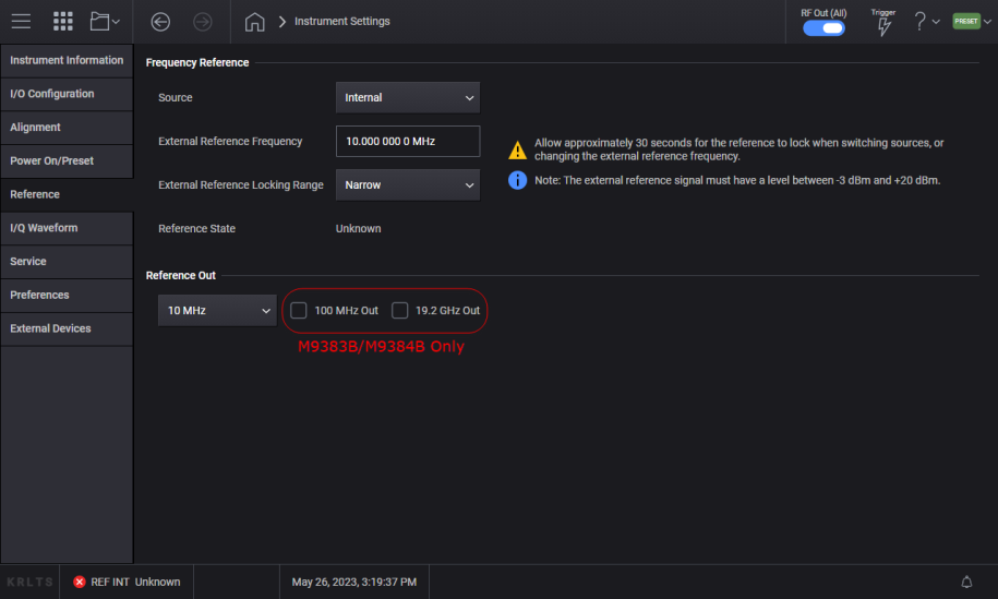
The Reference tab lets you configure the frequency reference for the instrument. For Option 1ER, the user interface appears and behaves differently.
|
GUI Location |
System Menu > Settings (gear icon) > Reference |
|
Initial S/W Revision |
A.01.00 |
|
Modified S/W Revision |
A.04.00 and A.11.00 |
Standard User Interface for Reference.
Option 1ER User Interface for Reference.
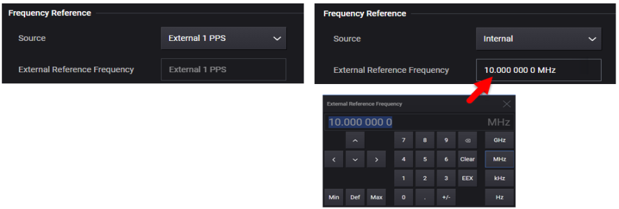
Selects the source for the frequency reference. Choices include the following:
Internal (instrument’s timebase)
External
External 1 PPS (Option 1ER only)
The selection appears in the reference indicator field of the notifications area at the bottom of the display. When set to External the frequency of the external signal can be specified with the External Reference Frequency setting.
If the external reference becomes unlocked or fails, after you correct the issue, toggle the Frequency Reference Source to Internal and back to External to update the Reference State status.
|
GUI Location |
System Menu > Settings (gear icon) > Reference > Source |
|
SCPI Command |
[:SOURce]:ROSCillator:SOURce INTernal|EXTernal|PPS [:SOURce]:ROSCillator:SOURce? |
|
Preset |
Not reset by Preset, set to INTernal with Restore System Settings to Defaults |
|
Notes |
Changing the reference may take up to 90 seconds to regain frequency lock. For remote control operation, ensure your VISA timeout is set to 90 seconds (or more) when executing this command. With standard configuration, attempting to set PPS will generate the error “703,Feature not supported; External PPS requires option 1ER” |
|
Initial S/W Revision |
A.01.00 |
|
Modified S/W Revision |
A.11.00 |
|
History |
Option 1ER added at A.11.00 |
The frequency of the external reference can be 10 MHz or 100 MHz. Additionally, with option 1ER the frequency can be 1 MHz to 110 MHz with 0.1 Hz resolution.
|
[GUI Location |
System Menu > Settings (gear icon) > Reference > External Reference Frequency |
|
SCPI Command |
[:SOURce]:ROSCillator:FREQuency:EXTernal <freq> [:SOURce]:ROSCillator:FREQuency:EXTernal? |
|
SCPI Example |
:ROSC:FREQ:EXT 100 MHZ |
|
Preset |
This is unaffected by a Preset but is set to 10 MHz on a "Restore System Settings to Default Values.” |
|
State Saved |
Persistent, survives preset and power cycle but not saved in the instrument state. |
|
Notes |
Changing the reference frequency may take up to 30 seconds to regain frequency lock. For remote control operation, ensure your VISA timeout is set to 30 seconds (or more) when executing this command. With standard configuration, the valid selections for <freq> are 10 MHz or 100 MHz. Any other value will generate the error “-221,Settings conflict” “703,Feature not supported; frequency value requires option 1ER” When Frequency Reference is set to PPS, attempting to change frequency value will raise the error “-221, Settings conflict; frequency value cannot be changed while set to External 1 PPS” |
|
Min |
With standard configuration: 10 MHz With Option 1ER: 1 MHz |
|
Max |
With standard configuration: 100 MHz With Option 1ER: 110 MHz |
|
Resolution |
With standard configuration: Not applicable With Option 1ER: 0.1 Hz |
|
Initial S/W Revision |
A.04.00 |
|
Modified S/W Revision |
A.11.00 |
|
History |
Option 1ER added at A.11.00 |
The instrument provides two locking ranges for an externally supplied reference signal. Locking range set to Wide allows your reference signal to be further away in frequency from the selected value in External Reference Frequency, with a slight compromise in the phase noise performance of the instrument. Locking range set to Narrow provides the best phase noise on the instrument, however, the reference signal must closer in value to the external reference frequency setting. See table below.
|
Locking Range |
External Reference Requirements |
Benefits |
|---|---|---|
|
Wide |
Within approximately +/- 1.0 ppm of the selected external reference frequency |
Easier to lock to external reference |
|
Narrow |
Within approximately +/- 0.6 ppm of the selected external reference frequency |
Better phase noise |
|
[GUI Location |
System Menu > Settings (gear icon) > Reference > External Reference Locking Range |
|
SCPI Command |
[:SOURce]:ROSCillator:FREQuency:EXTernal:LRANge NARRow|WIDE [:SOURce]:ROSCillator:FREQuency:EXTernal:LRANge? |
|
SCPI Example |
:ROSC:FREQ:EXT:LRAN WIDE |
|
Preset |
For M9383B/M9384B: This is unaffected by a Preset but is set to NARRow on a "Restore System Settings to Default Values.” For M9484C: This is unaffected by a Preset but is set to WIDE on a "Restore System Settings to Default Values.” |
|
State Saved |
Persistent, survives preset and power cycle but not saved in the instrument state. |
|
Notes |
For M9383B/M9384B: Beginning with S/W revision A.07.00 the default setting is NARRow, prior to A.07.00 the instrument was configured for NARRow and not changeable. |
|
Initial S/W Revision |
A.07.00 |
Displays whether the frequency reference is locked or if a failure occurred.
If the external reference becomes unlocked or fails, after you correct the issue, toggle the Frequency Reference Source to Internal and back to External to update the Reference State status.
The Ref Out connector is controllable. The connector is normally on, providing a 10 MHz frequency reference by default. The connector can be switched off, and in some model numbers of products the output frequency is selectable.
|
GUI Location |
System Menu > Settings (gear icon) > Reference > Reference Out |
|
SCPI Command |
:ROUTe[:CONNectors]:REFerence:ROUTput OFF|F10|F100 :ROUTe[:CONNectors]:REFerence:ROUTput? |
|
SCPI Example |
ROUT:REF:ROUT OFF |
|
Notes |
For M9383B, M9384B, or M9484C, can be F10 (10 MHz) or OFF. Attempting other selections on these models will raise the error 703,"Feature not supported; Reference Output frequency not changeable on this instrument." |
|
Preset |
This is unaffected by a Preset but is set to 10 MHz on a "Restore System Settings to Default Values." |
|
Save State |
Persistent, survives preset and power cycle but not saved in the instrument state. |
|
Initial S/W Revision |
A.12.00 |
For M9383B or M9384B, when checked this turns on the 100 MHz Out reference output signal. Leave this unchecked if you are not using this output, to minimize emissions.
|
GUI Location |
System Menu > Settings (gear icon) > Reference > 100 MHz Out |
|
SCPI Command |
:ROUTe[:CONNectors]:REFerence:LFOutput:STATe ON|OFF|1|0 :ROUTe[:CONNectors]:REFerence:LFOutput:STATe? |
|
Notes |
For models other than M9383B or M9384B the setting is accepted with no error raised. |
|
Preset |
On |
|
Initial S/W Revision |
A.01.00 |
For M9383B or M9384B, when checked this turns on the 19.2 GHz Out reference output signal. Leave this unchecked if you are not using this output, to minimize emissions.
|
GUI Location |
System Menu > Settings (gear icon) > Reference > 19.2 GHz Out |
|
SCPI Command |
:ROUTe[:CONNectors]:REFerence:HFOutput:STATe ON|OFF|1|0 :ROUTe[:CONNectors]:REFerence:HFOutput:STATe? |
|
Notes |
For models other than M9383B or M9384B the setting is accepted with no error raised. |
|
Preset |
Off |
|
Initial S/W Revision |
A.01.00 |
|
GUI Location |
System Menu > Settings (gear icon) > I/Q Waveform |
|
Initial S/W Revision |
A.06.00 |
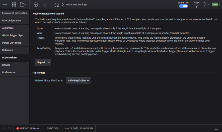
The instrument requires waveforms to be a multiple of 8 samples, and a minimum of 512 samples. You can choose how the instrument processes waveforms that do not match the instrument’s requirements as follows:
None: No extension is done. A warning message is shown only if the length is not a multiple of 8 samples.
Warn: No extension is done. A warning message is shown if the length is not a multiple of 8 samples or is shorter than 512 samples.
Repeat: The original waveform is repeated until the length satisfies the requirements. This yields the highest fidelity playback at the expense of larger waveform files. This is the most applicable under Trigger Mode of Continuous where playback continues when the end of the waveform has been reached.
Zero Padding: Samples with I=0 and Q=0 are appended until the length satisfies the requirements. This yields the smallest waveform at the expense of discontinuous playback. This is the most applicable under Trigger Mode of Single; and if using Single Mode of Restart on Trigger, the restart will occur even if trigger received during the zero padding period.
|
GUI Location |
System Menu > Settings (gear icon) > I/Q Waveform > Waveform Extension Method |
|
SCPI Command |
:MEMory:IMPort:WEXTension NONE|WARN|REPeat|ZPADding :MEMory:IMPort:WEXTension? |
|
SCPI Example |
:MEM:IMP:WEXT REP :MEM:IMP:WEXT? |
|
Preset |
This is unaffected by a preset, but is set to REPeat on a "Restore System Settings to Default Values” |
|
State Saved |
Persistent, survives preset and power cycle but not saved in the instrument state. |
|
Choices |
None | Warn | Repeat | Zero Padding |
|
Initial S/W Revision |
A.04.00 |
Sets the default binary file format used when reading waveform binary files. This affects simple binary data only and does not affect other formats such as secure waveform (wfm) file and Matlab file.
Selections are:
Int16 Big Endian
Int16 Little Endian
This setting does not affect the data currently selected. For example, if a binary file is selected by the File setting under Signal’s Waveform File mode, changing this setting doesn’t invoke reloading or reuploading of the file. The selected new file format is used when the file is set next time.
|
GUI Location |
System Menu > Settings (gear icon) > I/Q Waveform > Default Binary File Format |
|
SCPI Command |
:SYSTem:WAVeform:BFILe:FORMat:DEFault I16Big|I16Little :SYSTem:WAVeform:BFILe:FORMat:DEFault? |
|
SCPI Example |
:SYST:WAV:BFIL:FORM:DEF I16B |
|
Preset |
I16Big |
|
State Saved |
Persistent, survives preset and power cycle but not saved in the instrument state. |
|
Choices |
Int16 Big Endian | Int16 Little Endian |
|
Initial S/W Revision |
A.06.00 |
Accesses capabilities performed in the factory or under instructions from repair procedures.
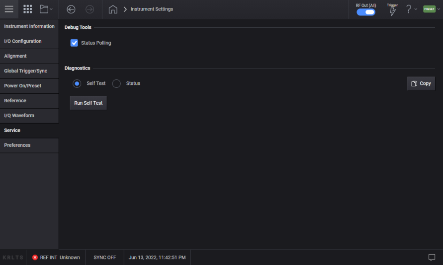
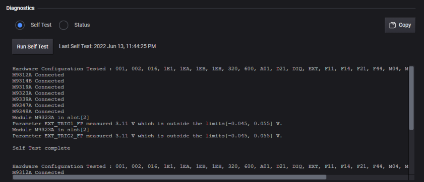
This area accesses self test and other diagnostic functions.
Selecting Self Test followed by Run Self Test displays diagnostic information for the installed modules. View ![]() example image.
example image.
For information on running the self test from SCPI see *TST? - Self Test Query
|
GUI Location |
System Menu > Settings (gear icon) > Service > Self Test |
|
Initial S/W Revision |
A.01.00 |
|
Modified S/W Revision |
A.11.50 Updated for M9484C |
Run Self Test takes at least five minutes to complete.
Copy simply copies this information to the clipboard for pasting into Windows programs.
This query performs the internal self-test routines for a specified RF Channel and returns a number indicating the success of the testing. A zero is returned if the test is successful, 1 if it fails.
|
SCPI Command |
:SYSTem:RF<channel>:STESt? |
|
SCPI Example |
SYST:RF3:STESt? !Runs the self-test routines for RF Channel 3 and returns 0=passed, 1=some part failed. |
|
Notes |
SYSTem:RF<channel>:STESt? May take many minutes to complete, set timeout value on controlling test program to a very large value (e.g. 10 minutes). Successful completion of self-test on the channel will clear the applicable bit in the STATus:QUEStionable:STFailed or STATus:QUEStionable:STFailed:ESTFailed register. Unsuccessful completion of self-test on the channel will set the applicable bit in the STATus:QUEStionable:STFailed or STATus:QUEStionable:STFailed:ESTFailed register. |
|
Initial S/W Revision |
A.11.50 |
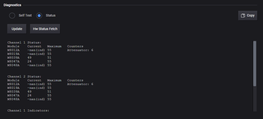
Selecting Status displays temperatures and other information for the installed modules. View ![]() example image.
example image.
|
GUI Location |
System Menu > Settings (gear icon) > Service > Status |
|
Initial S/W Revision |
A.01.00 |
|
Modified S/W Revision |
A.11.50 Updated for M9484C |
Copy simply copies this information to the clipboard for pasting into Windows programs.
|
GUI Location |
System Menu > Settings (gear icon) > Preferences |
|
Initial S/W Revision |
A.01.00 |
The instrument is delivered from the factory with the Model Number, Instrument Description and, in the case of the M9384B and M9484C, the Serial Number. TheM9383B does not have a serial number. For the M9383B and M9384B, there may be situations where the identification needs to be changed, such as if you are using a removable SSD and sharing a spare SSD between different VXG signal generators. You can change the Model Number and Serial Number in the Preferences tab in the System menu. The Description will be automatically selected based on Model Number.
|
GUI Location |
System Menu > Settings (gear icon) > Preferences > Instrument Identification |
|
Initial S/W Revision |
A.04.00 |
Remote command only.
Configures the Attenuator Compatibility Mode. When in PSG mode, the coupling among Power, Attenuation, and ALC Level works in a similar way as the PSG. With this coupling, the Power is changed when the ALC Level is changed. In the VXG, Power is not clipped when the ALC Level goes to either max or min.
|
SCPI Command |
:SYSTem:COMPatibility:POWer:ATTenuator NORMal|PSG :SYSTem:COMPatibility:POWer:ATTenuator? |
|
SCPI Example |
SYST:COMP:POW:ATT PSG SYST:COMP:POW:ATT? |
|
Notes |
The setting is enabled by this command is not affected by signal generator power-on, preset, or *RST. |
|
Preset |
NORMal |
|
State Saved |
No |
|
Initial S/W Revision |
A.04.00 |
The following example shows how Power, Attenuation, and ALC Level change when Attenuator Compatibility Mode is PSG.
# Set Attenuator Compatibility Mode to PSG
-> :SYSTem:COMPatibility:POWer:ATTenuator PSG
# Set up the initial condition. ALC Level is set based on
-> :POWer -10dBm
-> :POWer:ATTenuation:AUTO OFF
-> :POWer:ATTenuation?
<- 0
-> :POWer:ALC:LEVel?
<- -10
# Increasing ATTen by 10 dB decreases Power by the same amount
# -20 dBm (= ALC Level - Atten)
-> :POWer:ATTenuation 10.0 dB
-> :POWer?
<- -20
-> :POWer:ALC:LEVel?
<- -10
# Change ALC Level changes Power
-> :POWer:ALC:LEVel -9 dBm
-> :POWer?
<- -19
# When Auto Atten is on (Atten Hold off), the equation
# Power = ALC Level - Atten
# doesn't hold.
# Note that Atten 70 dB in this example isn’t the actual Atten value.
# In VXG, the actual one is set only when Auto Atten is off.
-> :POWer:ATTenuation:AUTO ON
-> :POWer?
<- -19
-> :POWer:ATTenuation?
<- 70
-> :POWer:ALC:LEVel?
<- -9
# Changing Power doesn't change Atten nor ALC Level
-> :POWer -17.0 dBm
-> :POWer:ATTenuation?
<- 70
-> :POWer:ALC:LEVel?
<- -9
# When AUTO is off again, Atten and ALC Level are set to satisfy the equation.
# Power = ALC Level - Atten
-> :POWer:ATTenuation:AUTO OFF
-> :POWer?
<- -19
-> :POWer:ATTenuation?
<- 0
-> :POWer:ALC:LEVel?
<- -19
# When Power changes by a large amount, ALC Level exceeds the limit.
# In PSG, the both the power and ALC Level are clipped.
# On the other hand, in VXG, only ALC Level is clipped.
-> :POWer -37.0 dBm
-> :POWer:ATTenuation?
<- 0
-> :POWer:ALC:LEVel?
<- -20
-> :POWer?
<- -37
-> :SYST:ERR?
<- -222,"Data out of range;ALC Level value clipped to lower limit -20 dBm."
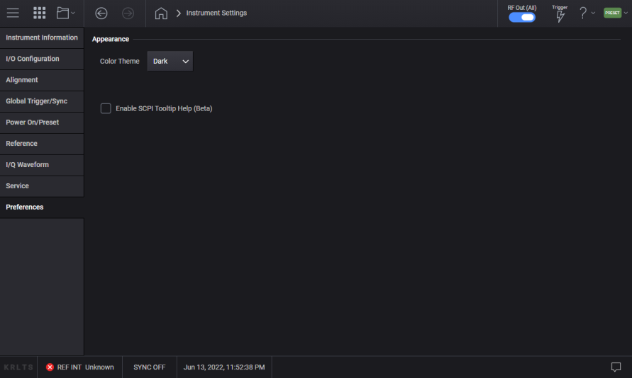
Bright Color (LIGHt) – Selects a full color palette for the display with dark text on a bright background.
Dark Color (DARK) – Selects a full color palette for the display with bright text on a dark background
|
GUI Location |
System Menu > Settings (gear icon) > Preferences > Color Theme |
|
SCPI Command |
:DISPlay:THEMe DARK|LIGHt :DISPlay:THEMe? |
|
SCPI Example |
SYST:DISP:THEM DARK |
|
State Saved |
Power On Persistent (survives shutdown and restart) |
|
Preset |
This is unaffected by a Preset but is set to DARK on a "Restore System Settings to Default Values” |
|
Initial S/W Revision |
A.04.00 |
Remote commands only.
The commands in this section have no front-panel key equivalent.
Remote command only.
This query returns a comma-separated list of installed software application options. This differs from the output for *OPT? in that the *OPT? lists the installed hardware options.
|
SCPI Command |
:DIAGnostic[:CPU]:INFormation:OPTions? |
|
SCPI Example |
:DIAG:INF:OPT? |
|
State Saved |
No |
|
Initial S/W Revision |
A.01.00 |
Remote command only.
Performs the same functionality as the Win+L function or the "Lock" function on the CTL-ALT-DEL screen in Windows.
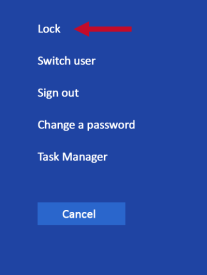
When this command is executed, the computer is immediately locked. The initial login screen appears; no one can access the computer at this point unless they have an account and know the account’s password.
If it fails to initiate it puts an error in the Windows event log for M9383B/M9384B;
"LockWorkStation - Failed to initiate function"
|
SCPI Command |
:SYSTem:LWSTation |
|
SCPI Example |
:SYST:LWST |
|
Notes |
The lock remains in effect until someone logs in |
|
State Saved |
No |
|
Initial S/W Revision |
A.01.00 |
Remote command only.
Outputs a list of the valid SCPI commands for the currently selected Mode.
|
SCPI Command |
:SYSTem:HELP:HEADers? |
|
SCPI Example |
:SYST:HELP:HEAD? |
|
Notes |
The output is an IEEE Block format with each command separated with the New-Line character (hex 0x0A) |
|
Initial S/W Revision |
A.01.00 |
Remote command only.
Determines the instrument application start time.
|
SCPI Command |
:SYSTem:METRics:STIMe? |
|
SCPI Example |
:SYST:METR:STIM? |
|
Notes |
The return value is a string with the format “YYYY-MM-DD<space>HH:MM:SS”, in instrument local time. |
|
Initial S/W Revision |
A.01.00 |
Remote command only.
Returns the SCPI version number with which the instrument complies. The SCPI industry standard changes regularly. This command indicates the version used when the instrument SCPI commands were defined.
|
SCPI Command |
:SYSTem:VERSion? |
|
SCPI Example |
:SYST:VERS? |
|
Initial S/W Revision |
A.01.00 |
Remote command only.
Returns the cumulative number of times that the attenuator has been switched. The subopcode indicates the channel being queried.
|
SCPI Command |
:DIAGnostic[:CPU]:INFormation:CCOunt:ATTenuator[1]|2? |
|
SCPI Example |
:DIAG:INF:CCO:ATT? |
|
Initial S/W Revision |
A.01.00 |
Remote command only.
Returns the cumulative number of times that the attenuator bypass has been switched. The subopcode indicates the channel being queried.
|
SCPI Command |
:DIAGnostic[:CPU]:INFormation:CCOunt:ATTenuator[1]|2:BYPass? |
|
SCPI Example |
:DIAG:INF:CCO:ATT:BYP? |
|
Initial S/W Revision |
A.01.00 |
Remote command only.
Returns the cumulative number of times the signal generator has been powered–on.
|
SCPI Command |
:DIAGnostic[:CPU]:INFormation:CCOunt:PON? |
|
SCPI Example |
:DIAG:INF:CCO:PON? |
|
Initial S/W Revision |
A.01.00 |
Remote command only.
Returns the cumulative number of hours the signal generator has been on.
|
SCPI Command |
:DIAGnostic[:CPU]:INFormation:OTIMe? |
|
SCPI Example |
:DIAG:INF:OTIM? |
|
Initial S/W Revision |
A.01.00 |
Remote command only.
Returns the CPU’s BIOS version in the format provided by the CPU manufacturer.
|
SCPI Command |
:DIAGnostic[:CPU]:BIOS:VERSion? |
|
SCPI Example |
:DIAG:BIOS:VERS? |
|
Notes |
Return value is a string of the BIOS version in the format provided by the controller’s manufacturer. |
|
Initial S/W Revision |
A.09.00 |